Do you have a question about the Spirax Sarco AEL52213 and is the answer not in the manual?
Essential safety precautions for electrical wiring and connections.
Covers EMC, CE marking, and product suitability for application.
Covers access, lighting, hazards, system, pressure, tools, and clothing.
Addresses permits, handling, residual hazards, freezing, disposal, and returns.
Overview of AEL5 actuator applications and available supply variants.
Details on normal motor operation and manual handwheel operation.
Guidelines for actuator mounting location and environmental considerations.
Procedures for attaching AEL5 actuators to various valve types.
Instructions for accessing and reassembling the actuator cover.
Steps for installing positioner cards for analog control signals.
Procedures for fitting limit switches, potentiometers, and heaters.
Essential wiring information, including VMD, positioner card, and accessory connections.
Initial checks and specific commissioning steps for 2-port and 3-port valves.
Detailed steps for setting up positioners with analog control signals.
Guidance on inspecting, lubricating, and replacing the spindle nut.
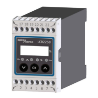
| Type | Electronic Level Controller |
|---|---|
| Output | SPDT Relay |
| Max Switching Voltage | 250 VAC |
| Operating Temperature | -10°C to +60°C |
| Application | Liquid level control in boilers and tanks |
| Probe Length Options | Multiple lengths available (e.g., 300mm, 450mm, 600mm) |