19
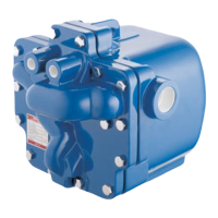
Step 4 (Figure 8)
The snap action mechanism ensures
a rapid change from the trapping
mode to the active pumping mode.
With the motive inlet valve open, the
pressure in the APT14, APT14HC
and APT14SHC increases above
the total backpressure and the
condensate is forced out through
the trap seat into the plant’s return
system.
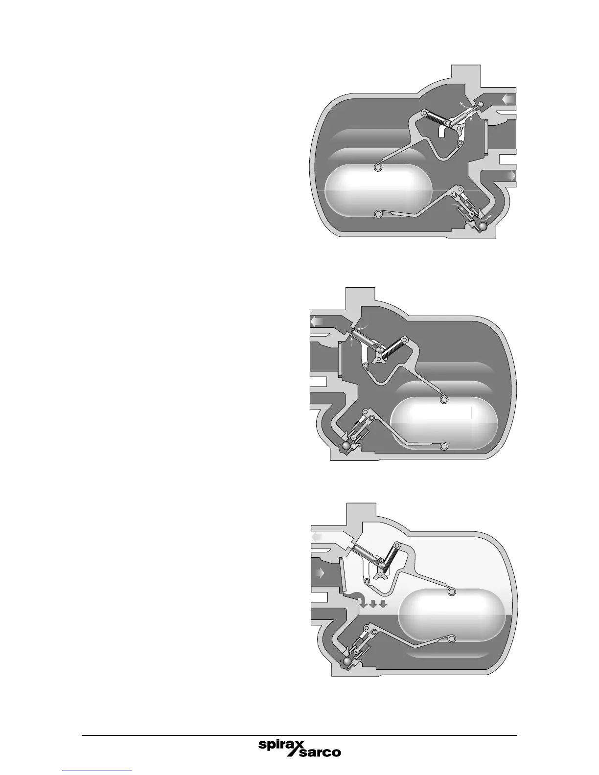
Step 5 (Figure 9)
As the condensate level falls
within the main chamber, the
float re-engages the change
over linkage, causing the motive
inlet to close and the exhaust
valve to open.
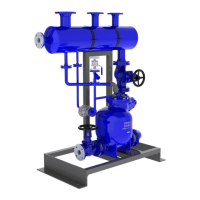
Step 6 (Figure 10)
As the pressure inside the APT14
equalises with the condensate inlet
pressure through the open exhaust
valve, condensate re-enters via
the inlet swing check valve. At the
same time the outlet ball check
valve (APT14 only) ensures no
condensate can drain back into the
main chamber and the trapping or
pumping cycle begins again.
Note: The APT14HC and
APT14SHC requires an external
Spirax Sarco DN40 disc check
valve to be fitted to the condensate
outlet, between the flanges.
Fig. 10 APT14 shown
Fig. 9 APT14 shown
Fig. 8 APT14 shown
Motive
steam
inlet
Condensate
inlet PS
Exhaust
Condensate
outlet PB
Condensate
inlet PS
Exhaust
Condensate
outlet PB
Return to Step 1.