22
4.1 Inlet piping
To prevent condensate backing up into the equipment being drained, it is recommended that
the inlet pipework is sufficiently sized to accumulate condensate during the pump’s discharge
cycle. Generally a length and diameter of pipe to accommodate the following condensate
capacity will be sufficient: 4 litres (1.1 gallons) for an APT14 or 8 litres (1.76 gallons) for an
APT14HC and APT14SHC. It is recommended this condensate reservoir is situated at least
1 pipe diameter below the process outlet but as high as possible above the APT inlet (up to
1 metre (40")). It is essential that a Spirax Sarco Y-type strainer is fitted at the condensate
inlet of the APT14, APT14HC and APT14SHC, as shown in Figure 12.
4.2 Recommended installation head
An installation head of at least 0.3 m (12 ins) from the base of the unit is recommended.
Minimum 0.2 m (8") with reduced capacity; Maximum 1 m (40"). Note: During cold start-up
conditions, it is possible for hydraulic pulsing of the inlet check valve to occur. It is advisable
in this case to install a throttling isolation valve to reduce the filling pressure.
4.3 Connections (refer to the installation diagram, Figure 12)
The APT's have four connection ports. The DN40 (1½") - APT14 or DN50 (2") - APT14HC
and APT14SHC port should be connected to the outlet of the equipment being drained.
The DN25 (1") - APT14 or DN40 (1½") APT14HC and APT14SHC port should be connected
to the condensate return line. Flow arrows indicate the correct direction of flow. The DN15
(½") port marked (S) should be connected to a trapped motive steam supply. * It is
important to ensure this line is drained of condensate at all times using a Spirax
Sarco steam trap and filtered using a 100 mesh strainer as fitted (see Figure 11).
The screwed DN15 (½") port marked (E) should be balanced back as close as possible
to the condensate outlet of the equipment. This balance line must always be connected
to the top of the condensate pipe, as shown in Figure 11. Note: If a thermal cut out device
has been installed to protect the heat exchanger from excess temperature, then it is
important this is mounted upstream of the steam control valve and the take-off point for
the motive steam supply to the APT14, APT14HC or APT14SHC.
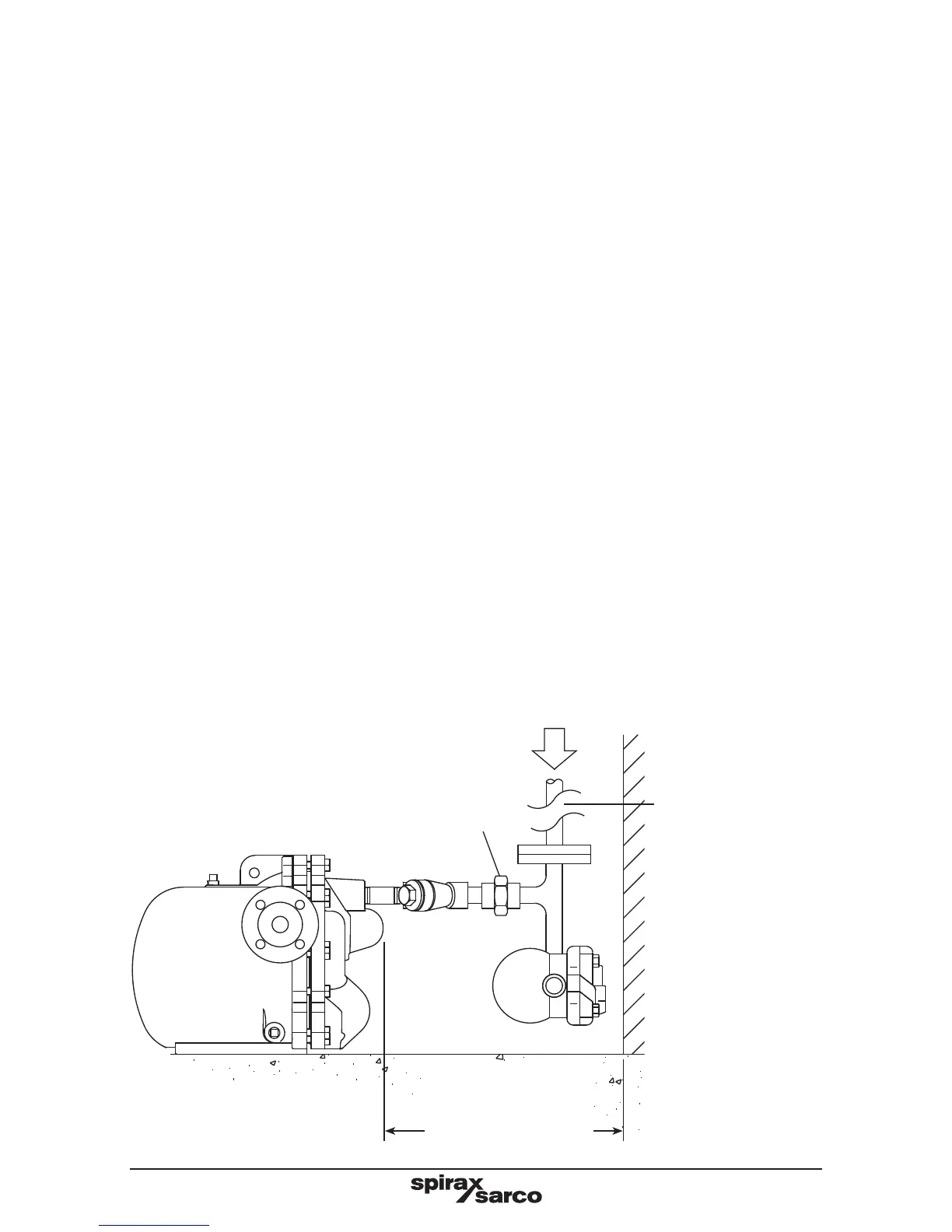
Filtered / trapped motive steam supply line
Removable flanged or union section for
ease of maintenance
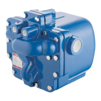
Spirax
Sarco
APT14
•
Ensure this
steam line is
correctly drained
of condensate at
all times using a
Spirax Sarco steam
trap plus the 100
mesh strainer as
fitted to the pump
to prevent debris
entering the pump
mechanism.
Fig. 12
Suggested coupling of
motive supply and exhaust
lines
250 mm (APT14)
275 mm (apt14hc
275 mm (APT14SHC)
minimum withdrawal
distance