24
4.5 Pressure gauges
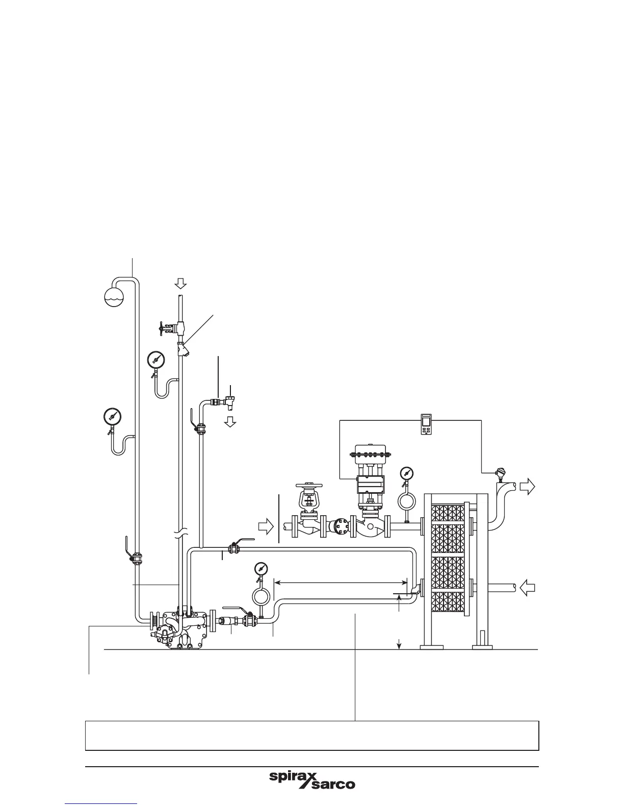
It is recommended that system pressure gauges are fitted to the motive supply, condensate
inlet and condensate outlet as shown in Figure 14.
4.6 Control of motive supply pressure
Although the APT is able to utilise motive pressures up to 13.8 bar g (200 psi g), it is highly
recommended that the motive pressure does not exceed 3 to 4 bar g (44 to 58 psi g) above
the backpressure applied to the pump. When specifying a pressure reducing valve to
reduce the motive supply pressure, the effects of pulsating flow on the pressure reducing
valve must be considered. Contact Spirax Sarco for details of recommended installation if
required. The motive supply must be drained by a suitable steam trap to ensure the motive
steam is dry. See Figure 14.
Motive IN
Strainer fitted with 100 mesh screen.
Note: The APT's are all supplied with a strainer close coupled
to the steam inlet connection.
Spirax Sarco sized length
of pipe to act as a reservoir
Balance
line
Exhaust
OUT
Condensate inlet
Strainer
Outlet DCV10 between flanges
(APT14HC and APT14SHC only)
An air vent must be fitted higher than the inlet to the process.
†
Fig. 14
Soft sealing flanged or screwed DCV
0.2 m
(8")
It is recommended that the reservoir be installed at least 1 pipe diameter below the
process outlet, but as high as possible above the APT14, APT14HC or APT14SHC inlet.
Condensate
outlet
*Trapped motive steam supply
† Minimum installation head
0.2 m (8") from base of pump.
Recommend minimum 0.3 m,
maximum 1 m.