3
1. Before installation, inspection or maintenance, the
trap must be isolated from both supply and return
line pressure.
2. The trap should be installed below the drainage
point of the equipment or steam main so that
condensate can flow by gravity into the trap. A
vertical drop to the trap is advantageous, but long
horizontal runs should be avoided because of the
possibility of steam locking. If a long horizontal
run to the trap is unavoidable, a trap with a steam
lock release should be used.
3. If possible, a drop leg and dirt pocket should be
installed ahead of the trap. The trap should be
protected by a Spirax Sarco y-pattern stainer,
preferably fitted with a blow down valve. Full-port
isolating valves should be installed to permit ser-
vicing.
4. The trap must be installed in an upright posi-
tion with the orientation arrow on the body or on
the nameplate pointing straight down. The flow
direction markings on the body or cover must be
observed.
5. Before installing the trap, the inlet piping should
be carefully blown down to remove any existing
debris.
6. A Spira-tec
®
sensor chamber facilitates checking
the trap’s operation. A check valve downstream of
the trap will prevent backflow from the return line.
Installation
Description and Operation
Spirax Sarco Float & Thermostatic Steam Traps are ideally suited for most HVAC and process applications. The
spherical stainless steel float automatically adjusts the position of the main valve so that condensate is discharged
continuously at the same rate as it enters the trap. Air and other non-condensible gases which are present at start up
or which enter the trap during operation are discharged through the integral balanced pressure thermostatic air vent
(some high pressure F & T traps have a bimetal air vent). The traps will operate against any back-pressure lower than
the inlet pressure. (The differential pressure—inlet pressure minus outlet pressure—determines the trap’s capacity).
All Spirax Sarco F & T traps will tolerate at least 450°F of temperature. The superheat tolerance of some models is
higher; refer to the appropriate Technical Information Sheet or call Spirax Sarco for further information.
Limiting Operating Conditions
The maximum operating pressure (PMO) is shown on the nameplate. The PMO depends on the valve mechanism;
if the pressure at the trap inlet is higher than the PMO, the excess pressure may lock the valve closed. In some cases
(for example, if there is a permanent back-pressure in the return line) in may be permissible to exceed the PMO.
Please consult Spirax Sarco for details.
The maximum operating temperature depends on the superheat tolerance of the air vent. This is always at least
450°F as the TMA (see below) is not exceeded.
The maximum allowable pressure and temperature (PMA and TMA) are determined by the pressure shell design
conditions, and must not be permanently exceeded. The trap may be subjected to a temporary cold hydraulic test
pressure of 1-1/2 times the cold PMA, provided that the air vent is first removed. If the test pressure will exceed 600
psi, the float must also be removed.
7. If the condensate must be lifted to the return
main, the trap, followed by a check valve, should
be installed at the bottom of the lift. Sufficient
pressure to lift the condensate (approximately 1
psi for each 2 ft. of lift) must be present at the trap
inlet at all times.
Note that a temperature control valve on the
inlet steam may at times reduce the pressure
below the amount required to lift the condensate.
When the inlet steam is controlled and conden-
sate must be lifted after the trap, a Spirax Sarco
Pressure Powered Pump™ should be considered.
8. Bypass piping is not recommended because of
the possibility of misuse. If continuous service is
required, a second trap could be piped in paral-
lel with suitable valving to allow one trap to be
serviced while the other remains in operation. If
a bypass line must be used, it should be at least
one pipe size smaller than the trap.
9. Because condensate cannot drain completely
from the body, an F & T trap installed outdoors
can freeze up if it is not in continuous operation.
If there is a possibility of an interruption in the
steam supply, provisions should be made for
draining or tracing the trap body.
10.The trap can be put into service by slowly opening
the isolating valves. No priming is necessary.
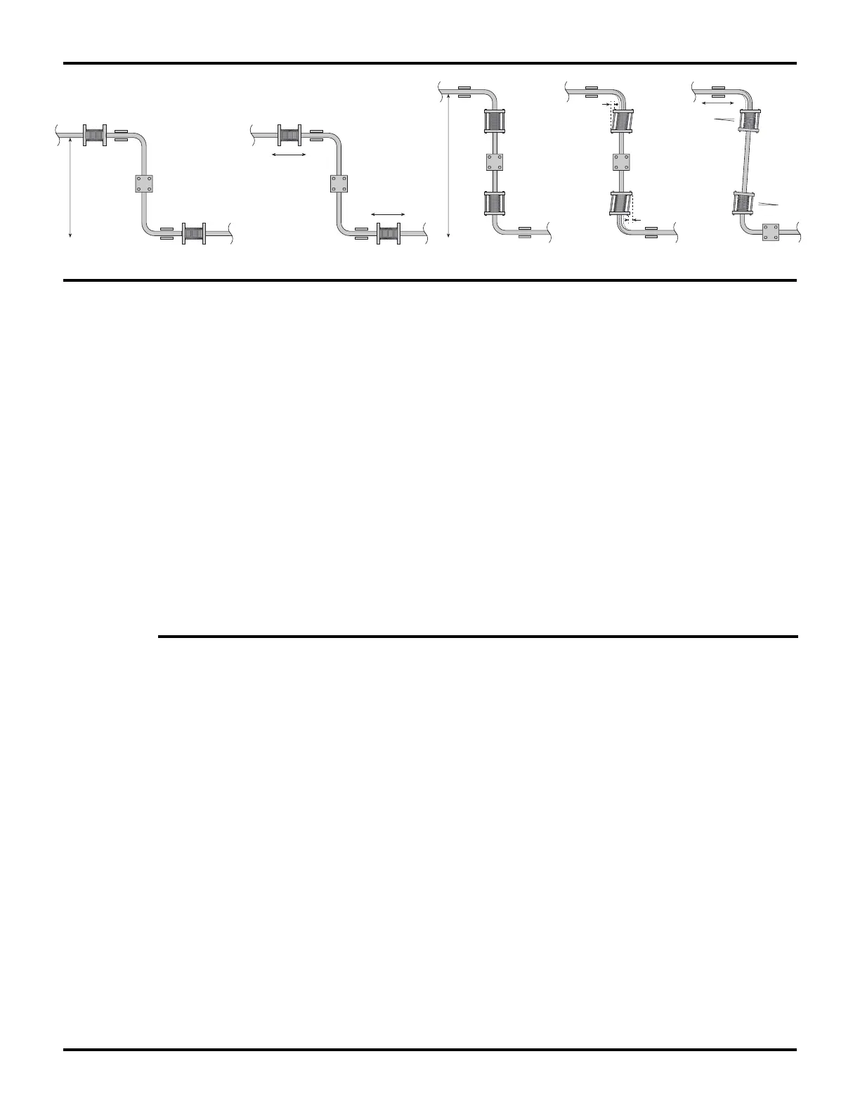
Thermal expansion:
Short
distance
Fixing point
Axial movement
Axial movement
Guides
Guides
Guides
Guides
Limit rods
Limit rods
Fixing point
Medium
distance
Small
lateral
movement
Small
lateral
movement
Large
lateral
movement
Large
lateral
movement
 Loading...