Do you have a question about the Spirax Sarco FT14 and is the answer not in the manual?
Defines the product's intended application and fluid compatibility, complying with regulations.
Ensures safe access, working platforms, and adequate lighting for maintenance and installation tasks.
Considers pipeline hazards like liquids/gases and environmental risks like temperature extremes.
Evaluates system-wide risks and details safe procedures for isolating and venting pressure systems.
Advises on temperature normalization and stresses the importance of using correct tools and genuine parts.
Recommends protective clothing and outlines requirements for competent supervision and safety permits.
Advises on safe handling of products and warns about residual hazards like hot surfaces.
Mandates protection against frost damage and states the product is recyclable with no ecological hazard.
Requires hazard information for returned products as per EC Health, Safety, and Environment Law.
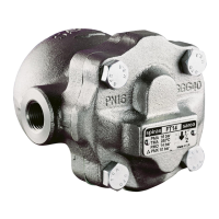
Describes the FT14 ball float steam trap, its features, construction, and connection options.
Lists available sizes and types of pipe connections for the steam trap, including screwed and flanged.
Provides critical pressure and temperature operating limits according to ISO 6552 standards.
Verifies product suitability for system pressure, temperature, and intended use before installation.
Determines the correct installation situation and direction of fluid flow for optimal performance.
Instructs to remove protective covers and film from connections and name-plates before installation.
Outlines general maintenance procedures including isolation, cooling, and reassembly of joint faces.
Details the steps for removing, replacing, and refitting the main valve assembly and its components.
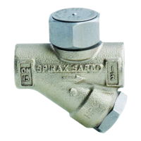
Describes the process for removing and refitting the air vent assembly, including seat and frame.
Lists the components available as spare parts for the steam trap, differentiating between supplied and non-supplied parts.
Provides instructions on how to order spare parts, specifying the required description and trap details.
The Spirax Sarco FT14 is an SG iron-bodied ball float steam trap designed for efficient condensate removal and air venting in steam systems. This device is suitable for use on steam, air, or condensate applications, with specific guidance provided for other fluids upon consultation with Spirax Sarco. It is engineered to comply with the Indian Boiler Regulations, 1950, and is available with a manufacturer's Typical Test Report and IBR certification upon order placement.
The FT14 operates as a continuous discharge trap, removing condensate as soon as it forms. Its design incorporates stainless steel working internals and an integral automatic air venting facility. During start-up, a thermostatic air vent allows air to bypass the main valve, preventing air binding within the system. As hot condensate enters the main chamber, the float rises, activating a lever mechanism that opens the main valve. This action ensures continuous drainage of condensate from the system. When steam arrives, the float drops, closing the main valve. This mechanism makes the FT14 well-suited for handling high start-up loads, providing clean, tight shut-off, and offering resistance to waterhammer and vibration. The BP99/32 capsule, integrated into the FT14, is specifically designed for use in superheat applications.
The FT14 is designed for ease of installation and maintenance without disturbing existing pipework. It is available with either horizontal screwed or flanged connections, supporting flow from right-to-left (R-L) or left-to-right (L-R). A vertical connection option (FT14V) is also available for downward vertical flow. The connection orientation can be changed on-site by loosening the four cover bolts and repositioning the cover to the desired orientation, though a new gasket must always be fitted during this process.
Proper installation requires the trap to be fitted with the float arm in a horizontal plane, ensuring it rises and falls vertically. The arrow on the name-plate must point downwards to indicate the correct fluid flow direction. It is crucial to check material suitability, pressure, and temperature limits against the system's operating conditions. If the product's maximum operating limits are lower than the system's, or if a malfunction could lead to dangerous overpressure or overtemperature, a safety device must be incorporated into the system. The product is not designed to withstand external stresses from the system, and installers are responsible for minimizing such stresses. Protective covers and films should be removed from connections and name-plates before installation, especially in high-temperature applications.
For optimum performance, the maximum operating pressure for saturated steam service (PMO) should not exceed 14 bar g. The product must not be used in regions where the pressure/temperature curve indicates unsafe operation.
Maintenance of the FT14 is designed to be straightforward, with specific instructions to ensure safety and proper function. Before any maintenance, the trap must be isolated from both the supply and return lines, and all pressure safely vented to atmosphere. The trap should then be allowed to cool. All joint faces must be clean during reassembly.
The cover gasket, which contains a thin stainless steel support ring, requires careful handling and disposal to prevent physical injury.
Main valve assembly replacement:
Air vent assembly replacement:
Recommended tightening torques for various components are provided:
Spare parts are clearly identified in the manual, with parts available for purchase shown in solid outline in the diagrams. These include the main valve assembly with float, air vent assembly, cover gasket (packet of 3), and a complete maintenance kit. When ordering spares, it is essential to use the provided descriptions and state the trap's size and type.
After any installation or maintenance, the system must be fully commissioned, and tests carried out on any alarms or protective devices to ensure full functionality.
| Connection Type | Flanged |
|---|---|
| Connection Size | DN15 to DN50 |
| Body Material | Carbon Steel |
| Pressure Rating | PN16, PN25, PN40 |
| Application | Steam |
| Type | Float Trap |