4
Maintenance
1. After isolation from supply and return line pres-
sure, all Spirax Sarco F & T traps can be serviced
without disturbing the piping connections. On some
models the cover with mechanism attached can be
removed for servicing while the body remains in the
pipeline.
2. On most models, dirt and sludge which may accu-
mulate in the trap can be removed by “blowing
down” through the drain plug in the bottom of the
body.
3. The trap should be disassembled periodically for
inspection and replacement if necessary of the
valve mechanism and air vent.
4. Ensure that the trap is properly isolated, and that
any pressure which may remain in the trap is
relieved before the trap is opened. This can be
accomplished by opening the blowdown valve on
the upstream strainer and waiting until the trap has
cooled. Some condensate will remain in the trap
body. This can be drained by removing the drain
plug or by cracking the body-cover joint.
5. Remove and save the cover bolts, and remove
the body or cover. Using a suitable solvent, clean
all dirt and incrustation from the body, cover and
mechanism. Inspect the body and cover for con-
densate corrosion.
6. Inspect the valve head and seat for damage, wear
or wiredrawing. Replace the mechanism if neces-
sary, using a complete valve mechanism kit and
following the instructions included with the kit.
7. Inspect the float for leakage or damage, and
replace if necessary. A distorted or collapsed float
is evidence of a severe and dangerous overpres-
sure or waterhammer condition which must be cor-
rected before the trap is returned to service.
8. The air vent should be removed, tested for proper
operation, and replaced if necessary. Instructions
are included with the air vent kit.
9. Remove all traces of the old gasket from the body
and cover, and ensure that the gasket surfaces are
clean and undamaged. Using a new cover gasket,
reassemble the trap. Tighten the cover bolts to the
torque shown on page 3.
10.The trap can be returned to service by slowly open-
ing the isolating valves. Priming is not required.
Note: Flash steam is formed when a portion of the
hot condensate re-evaporates as it passes from
a higher to a lower pressure (for example, as it
flows through a steam trap). This flash steam is
normal, and it should not be mistaken for live steam
leakage when the operation of the trap is being
observed.
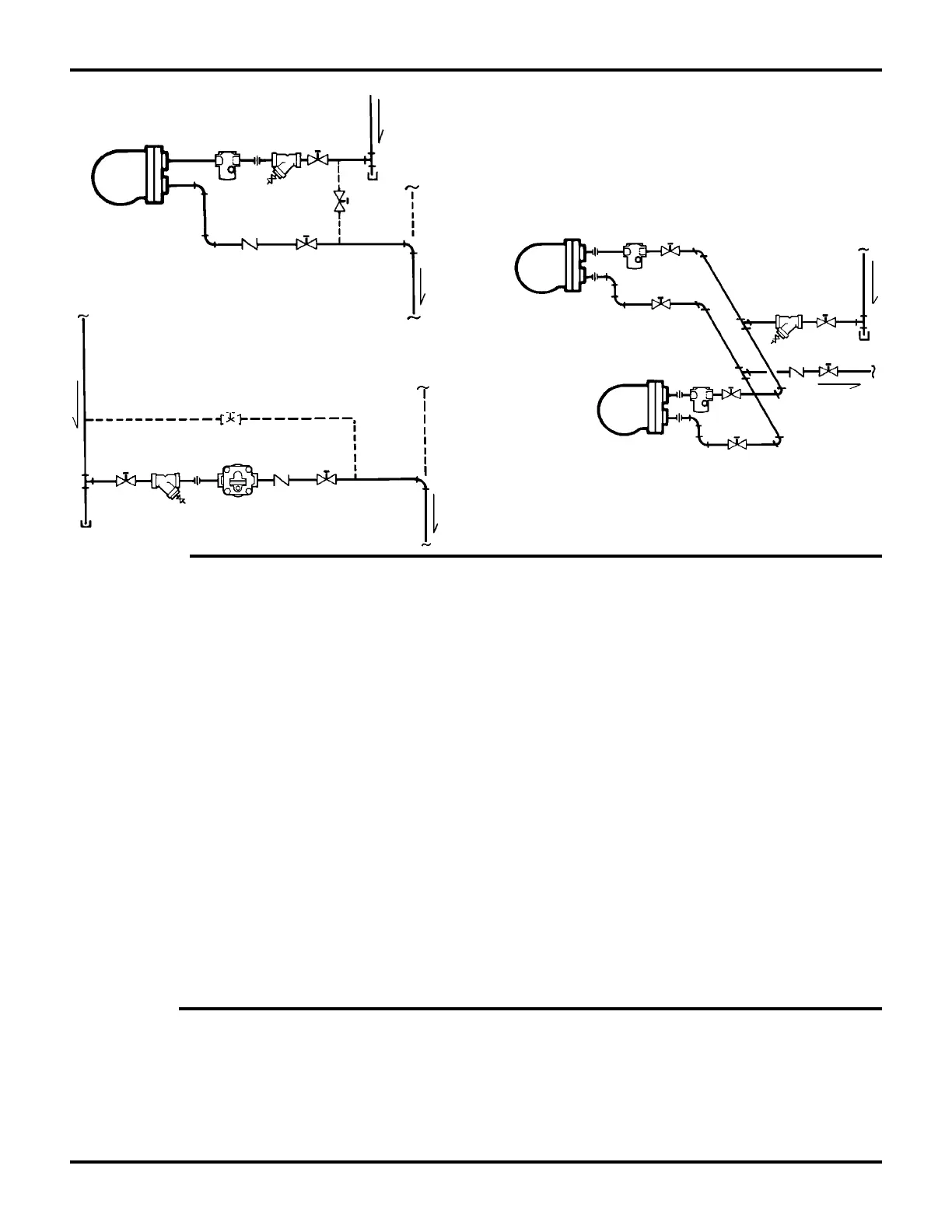
Horizontal Inline Type
Parallel Trap Installation
(No Bypass)
Parallel Type
Bypass
if required
Spira-Tec
C.V.
Bypass
if required
Str.
C.V.
Str.
Spira-Tec
C.V.
Spare Parts
The following spare parts are available for Spirax Sarco
Float & Thermostatic Steam traps:
Valve Mechanism Kit - Complete valve mechanism
with mechanism gasket and mounting screws as
required. A separate cover gasket kit should be
ordered when replacing mechanism parts.
Gasket Kit - Three each of cover and mechanism gaskets.
Air Vent Kit - Air vent assembly.
Replacement Kit - Valve mechanism with gasket, float
with screw and washer, air vent assembly, cover gasket.
Float Kit - Float with screw and lockwasher as required.
Note: In some models, the float is welded to the
mechanism arm, and is included in the valve
mechanism kit. A separate float kit is not available.
 Loading...