IM-P192-02 MI Issue 242
4.12 TVA communications
4.12.1 TVA UART set-up
The TVA flowmeter has an EIA 232C compatible communications link and supports two
protocols: a simple Line Feed [LF] terminated ASCII protocol and a subset of Modbus/RTU.
This enables users to easily interrogate the TVA flowmeter for steam data using either a dumb
terminal or a P.C. loaded with a simple terminal emulation program or a standard Modbus
Master / Client application. The connection length is limited to 15 metres and must be in the
same building / area as the TVA flowmeter.
The TVA’s communication set up should be as follows:
TVA ASCII set-up TVA Modbus set-up
Baud rate
1200 or 9600
Baud rate 1200 or 9600
Data bits
7
Data bits 8
Stop bits
one
Stop bits one
Parity
none
Parity none
Echo
off
Echo off
Response time:
The TVA will start responding within 500 msec. The actual time to fully receive a response
from the TVA is baud rate dependent, for example a Modbus poll of 12 registers @1200 baud
rate could take ((5 + 24) bytes x ~10 ms / byte) + 500 ms ≈ 800 ms to complete.
The polling frequency can be faster if the polling algorithm is set to poll immediately after
receiving a valid response to a poll.
4.12.2 Using the EIA 232C communications
It is assumed that:
-
The electrical wiring for the EIA 232C communications has been carried out in accordance
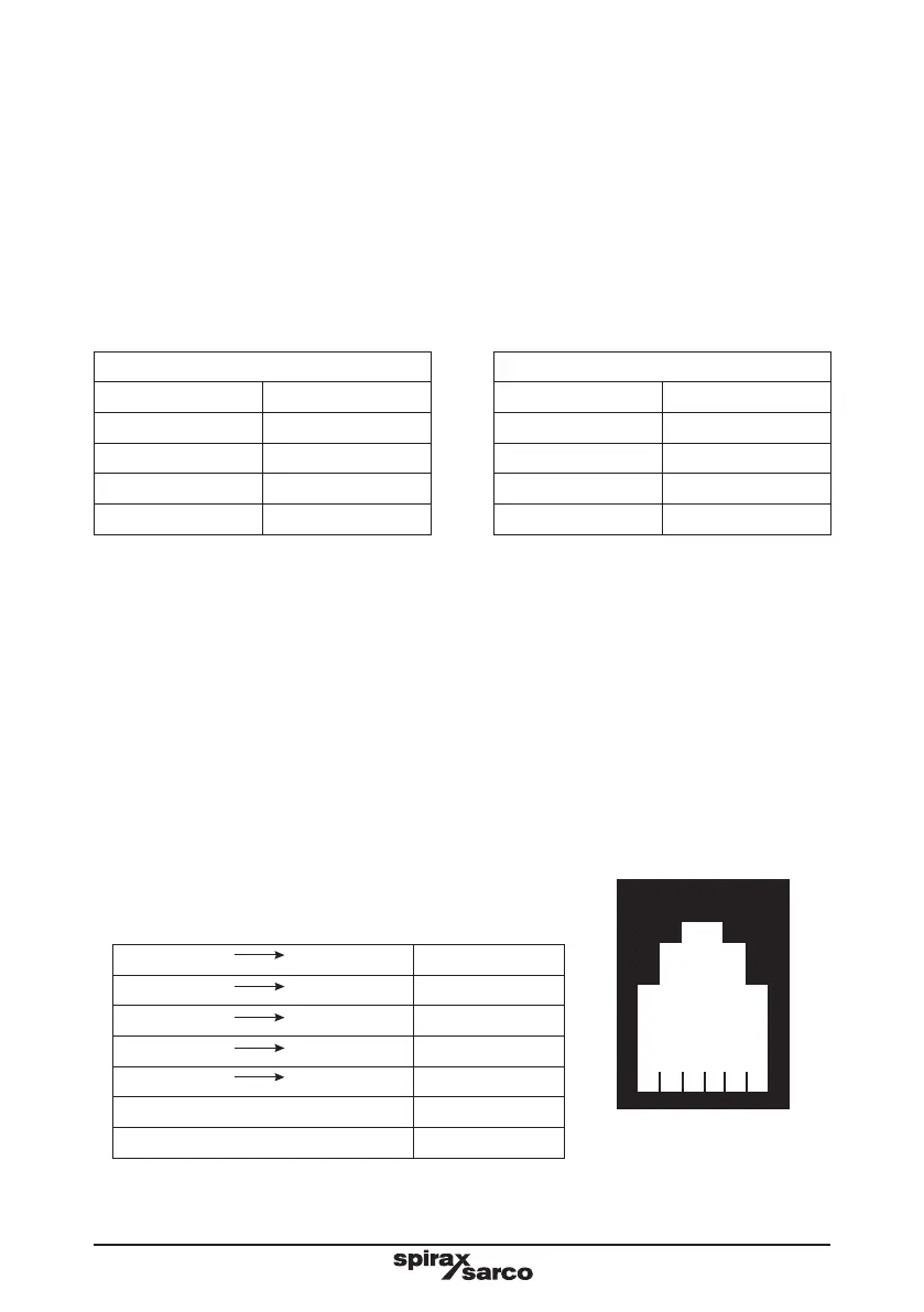
with the EIA 232C standard. Please note the TVA EIA 232C connection requires a
c o n n ec to r R J11 l i n ked t o a 9 w a y D - t y p e ad a pto r. Fi g ur e 2 5 i l lu s t r a t es t h e T VA ow m et e r 's
RJ11 socket from the front.
The table below lists the RJ11 socket's pin connections.
The signals are named from the PC (or data terminal) end.
RJ11 pin 9-way D-type Signal
1 Not used
2 4 DTR
3 5 GND
4 2 RX
5 3 TX
6 8 CTS
6 5 4 3 2 1
Pin numbers
Fig. 26 RJ11 socket

 Loading...


