Do you have a question about the Splendide 2100 and is the answer not in the manual?
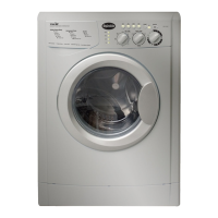
This document provides comprehensive information for the installation and use of the Splendide 2100 Laundry Center, model number WD2100 - (LD). It details the requirements for proper setup, electrical connections, drainage, and exhaust, ensuring safe and efficient operation of the unit. The information is crucial for both initial installation and ongoing maintenance.
The Splendide 2100 Laundry Center is designed for versatile installation, suitable for recessed areas, closets, or alcoves. When planning the installation, it's important to consider air space requirements to allow for easy installation, servicing, and compliance with state and federal codes. Specifically, a 0-inch clearance on the sides and a 1-inch clearance in the front and back (from the case) are recommended. The floor supporting the unit must be solid and capable of supporting at least 280 lbs. For installations in towable trailers or watercraft, the machine should be positioned over the axles or midship, where movement is minimal, and the unit must be blocked to prevent extreme movement.
For electrical connections, the laundry center operates on 115V, 13 Amp, 60Hz. It comes with a 6-foot, 3-prong plug for connection. The unit requires a 3-wire single phase, 120V, 60Hz, AC circuit, protected by a separate 15-ampere circuit. The electrical cord location is at the rear of the unit.
The standpipe drain system or sink draining requires a minimum 1 1/4-inch (3.2 cm) diameter standpipe with a minimum carry-away capacity of 7 gallons (26 liters) per minute. The top of the standpipe should be between 25 inches (62 cm) and 34 inches (86 cm) high from the bottom of the washer. The outlet end of the provided drain hose must be at least 20 inches above the bottom of the washer, and an air break must be available at the standpipe to prevent siphoning. For direct faucet connection, a Faucet Adapter Kit #154187104A is available. Detailed instructions for draining the hose directly into a sink, connecting to a dishwasher Wye fitting, or a disposer/drain connection are provided in the owner's manual. Optional Drain-A-Way™ Pans are also available, with Pan #PI-24 for cabinet or under-counter installations and Pan #P-24 for free-standing installations, both designed to be drain plumbed.
Exhaust requirements are critical for the dryer function. The dryer exhaust must NOT be directed into a chimney, furnace, cold air duct, attic, crawl space, or any other duct used for venting. If a cabinet door is installed, a minimum of 8 square inches of open space should be provided. Louvered doors with equivalent air openings are acceptable. Sufficient clearance behind the door(s) is necessary to prevent rubbing between the back of the cabinet door(s) and the front of the unit control panel. Additional clearances for walls, doors, and floor moldings may be required. A rigid or flexible metallic duct is required for venting, and the ducting must slope downwards and away from the machine to ensure proper operation and safety.
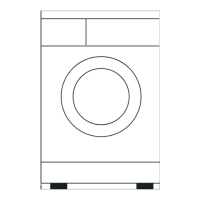
The physical dimensions of the unit are important for installation planning. The front view shows a width of 23-7/16 inches. The height can vary from 33-1/8 inches to 33-1/2 inches, depending on the positioning of the leveling legs. The depth from the front to the rear, excluding any protrusions, is 25 inches. The exhaust outlet is 4 inches in diameter and is located at the rear. The water inlets are also at the rear of the unit.
The side view provides additional depth measurements. The total depth, including the vent adapter and door handle, is 23-3/8 inches. The total case depth is 22-3/16 inches. The flexible drain hose provided is 5 feet in length and is secured with a plastic U-clamp. A minimum width of 24 inches for entry doors and hallways is recommended for ease of installation.
This data sheet serves as a guide for initial installation criteria. It is important to note that data sheets are subject to change without notice, and this document should not be reused for final installation criteria. Complete installation instructions are available upon request and are included in the owner's manual that accompanies the unit. Always refer to the most current and complete instructions for safe and proper installation and operation.
| Type | Washer/Dryer Combo |
|---|---|
| Width | 23.5 inches |
| Capacity (Wash) | 15 lbs |
| Capacity (Dry) | 11 lbs |
| Voltage | 120 V |
| Cycle Options | Heavy Duty, Normal, Delicate |