2 STG-02 – Service Test Generator
SPM Instrument AB • Box 4 • SE-645 21 Strängnäs • Sweden Technical data are subject to change without notice.
Tel +46 152 22500 • Fax +46 152 15075 • info@spminstrument.se • www.spminstrument.se © SPM 2002-01 71689.B
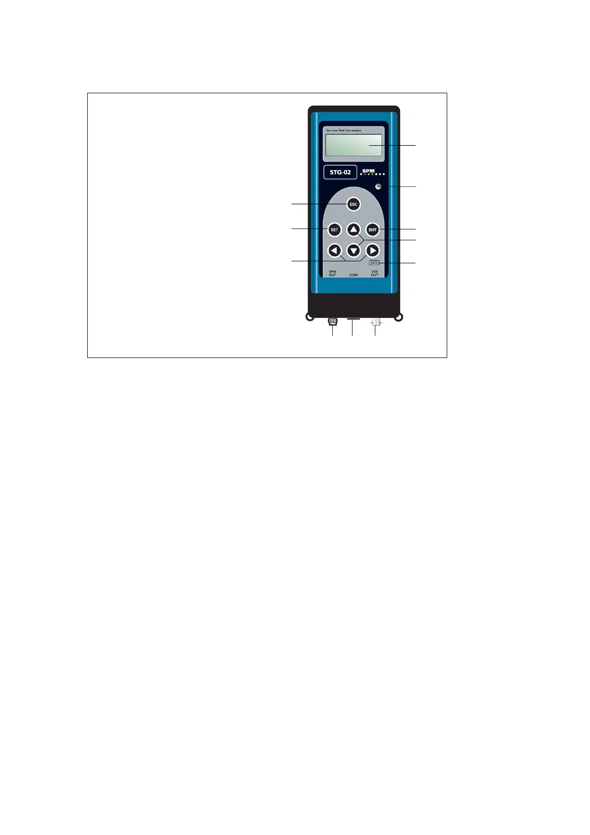
Instrument layout
1 Display 4x16 characters
2 Light sensor
3 Return key
4 Select key
5 ENTER key
6 Up/down keys
7 Left/right keys
8 OFF button
9 SPM connector
10 Communication connector
11 Vibration connector
6
7
1
2
5
4
8
9 10 11
Instrument layout
The instrument screen (1) is an LCD with back light, which can be turned off to
save battery power, or set to automatic, when it is controlled by a light sensor (2).
To start the instrument, press any of the dark keys. You can set a time for
automatic switch off or use the key (8) to turn it off.
Shock pulse signals are output from the TNC connector (9), vibration signals from
the BNC connector (11). The communication cable jack (10) receives a 6 pole
modular connector for connection to the communication module SPM 13603
which serves as interface with a PC.
3
 Loading...