Page 12 – Bulletin 100-50-5.1
provide efcient control. It may be necessary, however, to
ne tune the PID settings in applications where systems expe-
rience rapid transient conditions (such as frequent “impulse”
changes in loading or mass ow rates).
In most instances, adjustments to the PI setpoints are ad-
equate. If tuning is needed, see Section 3 - Setpoint Menu
Operation to enter the PID setpoint menu. The following
guidelines should be followed:
• p (Proportional Coefcient) - Increase value to
increase valve response to superheat.
• (Integral Coefcient) - Increase value to increase
valve response to superheat over a given time period.
• d (Derivative Coefcient) - Increase value to increase
valve response to rate of change in superheat.
•
• When PID adjustments are made, allow adequate time for
the system to respond to the changes.
When the superheat is oscillating to extremes, the Propor-
tional and/or the Integral value may be too high. If superheat
is slow to react to a transient system change, then the Propor-
tional and/or the Integral value may be set too low.
NOTE: Not all refrigeration systems are designed alike.
Use caution when tuning PID setpoints.
8. Troubleshooting
Troubleshooting Recommendations
As with any refrigeration component troubleshooting, actual
system conditions should be verified with a gauge set and a
calibrated temperature sensor (i.e verify actual superheat and
refrigerant condition). This system information is valuable in
determining whether it is component related or system related.
For systems or applications that experience light loads on
the Superheat Control circuit, it is important that the heat
exchanger and refrigerant lines are sized correctly. This will
ensure proper oil return and will minimize the effects of oil
logging in the heat exchanger. Many heat exchanger manufac-
turers recommend a hot gas bypass for loads below 50%.
Sensors
Failed sensors will trigger an alarm. An alarm code will show
which sensor is mis-wired, disconnected, or faulty. The alarm
will persist until the problem is corrected.
Failed temperature sensors may read extremely low or
innite resistance when tested with an ohmmeter. Readings
should be taken with the sensor disconnected from the Super-
heat Control. A missing or disconnected temperature sensor
will read 60 on the controller.
Temperature sensor output can be checked by measuring the
DC voltage across the sensor wires and consulting the tables
in Appendices L, M, N.
Pressure transducers must be installed tight enough to
depress the valve stem in the tting. Failure to do so will
result in erroneous pressure readings and possibly leaks.
Pressure transducers should be tested while connected to the
controller and powered. Test at the controller terminals. Volt-
age between terminals 34 and 35 should be 4.8 - 5.2 volts DC.
Voltage between 33 and 34 should be between 0.5 and 4.5
volts DC. See Table 1 - Pressure Transducer Wire Colors.
To test the accuracy of the transducer, use a gauge set to obtain
the actual system pressure. For volts-to-pressure conversion,
measure the voltage between terminals 33 and 34. Identify the
pressure transducer used and nd the correct range Prn in
Table 3. Substitute the measured voltage (v) into the formula
in the PSI column. The result should be within 3 psi of the ac-
tual system pressure shown on the gauge set. If not, check the
transducer for proper installation, correct Schrader valve, and
verify the pressure range identied on the transducer.
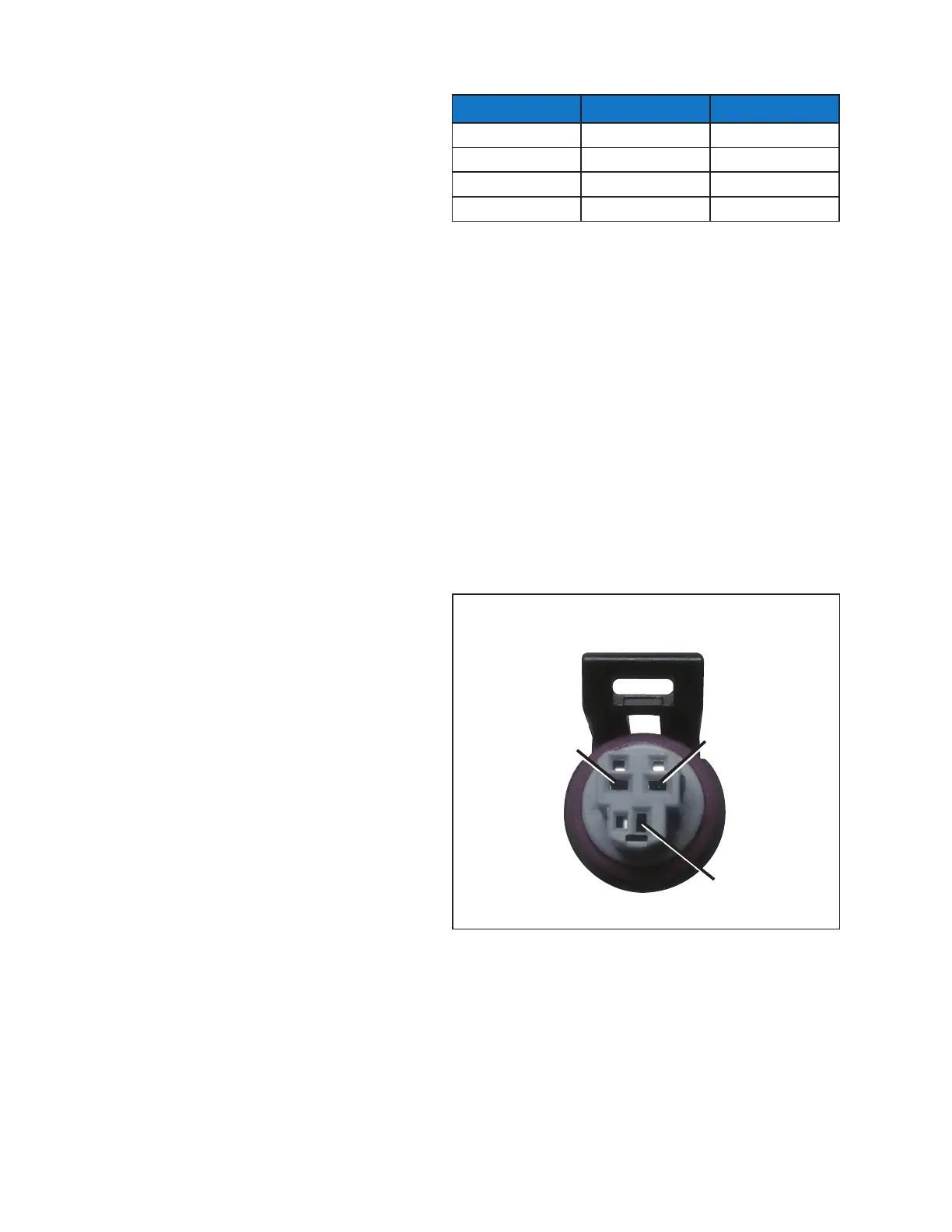
To test the transducer cable, disconnect the cable from the
transducer and check for 4.8 - 5.2 volts between terminals +
and – . See Figure 7 - Pressure Sensor Cable.
Alarms
The Superheat Control will display A when the system
detects a fault. The alarm feature noties the user on the dis-
play and through MODBUS or BACnet (when used). During
alarm, a voltage difference will occur across terminals 11/12
to support an external alarm relay. Note: Terminal 11 is not
part of the controller’s ground. See Table 4 for a list of alarms.
LABEL COLOR
Prn
PSI
Green 150 (v-.5) x 37.5
None / Silver 300 (v-.5) x 75
Yellow 500 (v-.5) x 125
Pink 652 (v-.5) x 163
Table 3 - Pressure Transducer Specifications
Figure 7 - Pressure Sensor Cable
S
–
+
+ Black
– Green
S White
 Loading...