Bulletin 100-50-5.1 – Page 9
R-410A: uses 0-300 psig
R-744 (Subcritical): uses 0-500 psig
All other common refrigerants: 0-150 psig
Ensure that this setpoint matches the corresponding pressure
sensor used on the system.
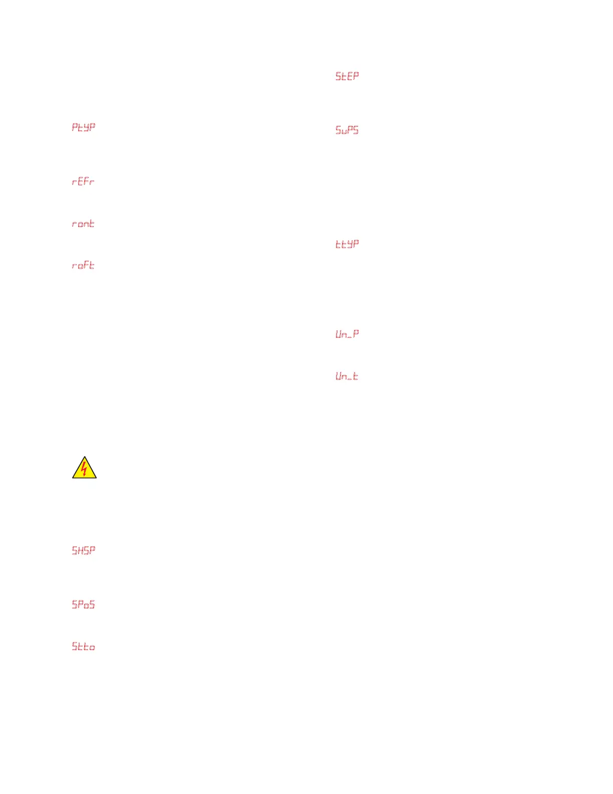
Ptp (Pressure Sensor Type) – The pressure sensor type,
such as gauge pressure, must be set correctly to properly mea-
sure suction pressure. Ensure that this setpoint matches the
corresponding pressure sensor used on the system.
rer (Refrigerant Type) – The system refrigerant type must
be set up in order to calculate and maintain superheat. The
Superheat Control has a list of commonly used refrigerants.
rnt (Relay On Time Minimum) – The amount of time, in
minutes, that the output of the relay terminals 19 and 20 must
remain on after it is energized. See below for more detail.
rFt (Relay Off Time Minimum) – The amount of time, in
minutes, that the output of the relay terminals 19 and 20 must
remain off after it is de-energized. See below for more detail.
On standalone systems, the rnt and rFt feature may be
used to prevent compressor short cycling when the Superheat
Control is used as a thermostat and Cut In/Cut Out tempera-
ture control is desired. The parameters C_n and Cvt must be
set as the temperature control range along with installation of
the room sensor, T2, to terminals 29 and 30. The minimum on
and off relay parameters should be set according to the com-
pressor manufacturer recommendations. When the Superheat
Control receives a pump down or call for defrost from the dry
contact at T3 temperature sensor input, terminals 27 and 28,
the system will not execute the procedure to pump down until
the minimum relay time has expired.
WARNING: The default setting for the Minimum
Relay On and Off time is 0 minutes. For a stand-
alone system these values may be adjusted to
prevent compressor short cycling.
NOTE: Use caution. An oversized compressor can cause
low case temperature during Minimum Relay On Time
cycle set by rnt.
SHSP (Superheat Setpoint) – The superheat setpoint is the
control variable. The Superheat Control uses system suction
pressure and temperature to calculate and maintain superheat
for a given refrigerant type.
SPS (Stepper Position) – The EEV position is shown on the
display real time in percent open. The position may also be
read through MODBUS or BACnet.
Stt (Stepper Timeout Override) – When the Stepper Time-
out Override is placed in the ‘on’ position, the system will
remain in manual valve mode indenitely and the standard 60
minute timeout will be disabled. It should be noted that the
setpoint parameter menu must be exited before changes are
saved. The valve position shown under SPS will blink when
the timeout is disabled. See Advanced Features section for
more information on manual valve mode.
NOTE: Use caution and monitor superheat while in manu-
al valve mode. To avoid floodback, start with the valve in a
low position. Never leave the system unattended while in
manual mode.
Step (Stepper Valve Type/Stroke) – The electronic valve
type must be set correctly to match the valve that is used on
the system. The type refers to the valve stroke, which typi-
cally is 2500 or 6386 steps.
SvPS (Supermarket Mode) – Supermarket Mode may be
used on large refrigeration systems; typically on controllers
that are used in refrigerated case line ups. This mode has a
unique algorithm to improve both case temperature pull down
and steady state control. If the Superheat Control is used on
standalone systems or systems with quick transient changes
in load, it is recommended to turn this mode off and manually
tune the PID parameters for the system. See PID tuning sec-
tion for more information.
ttp (Temperature Sensor Type) – The temperature sensor
type, such as 3K, must be set correctly to properly measure
temperature and calculate superheat. The Superheat Control
offers several types of temperature sensors; however, all
temperature sensors must be of the same type per controller.
Ensure that this setpoint matches the corresponding tempera-
ture sensor used on the system.
Un_P (Unit Type Pressure) – The pressure sensor units, such
as PSI, must be set correctly to properly measure and display
suction pressure.
Un_ (Unit Type Temperature) – The temperature sensor
units, such as Fahrenheit, must be set correctly to properly
measure and display temperature.
5. Display Networking
A Kelvin IId remote display unit can be connected to another
Superheat Control in order to set up that controller, view that
controller’s process values, and change setpoints.
To network a Superheat Control without display with a
Kelvin IId (remote display unit):
1. Connect the two controllers with a Cat-5 Ethernet cable.
2. The remote display unit will access the Superheat Control.
3. Set up the Superheat Control (Section 2 - Setup).
To network a Superheat Control without display with a
Superheat Control (with display):
1. Connect the 2 controllers with a Cat-5 Ethernet cable.
2. The Superheat Control with display must have its CAdr
parameter (Display Address) set to 1-99 to enable display
networking. Navigate to “End” in the process variables
display of the Superheat Control with Display and press
the SELECT knob to select a different controller on the
display network. (Controller should display “c”)
Note: “End” is not available if “CAdr” is 0.
3. Turn the SELECT knob to nd the Superheat Control
without display (2 is default for the Superheat Control
without display), and press the knob to connect.
4. After a connection is established the display should
switch from “----” to the rmware version of the
Superheat Control with display followed by the setup
screen (if the controller has not been set up as described
in Section 2).
 Loading...