2. Connect the suction temperature sensor wires to ter-
minals 31 and 32. Sporlan temperature sensors are not
polarized.
3. Connect the pressure transducer wires to terminals 33,
34, and 35. Sporlan has used transducer cables with two
wire color combinations; see Table 1. Maximum torque
on screw terminals is 3.5 in-lbs.
4. Connect the optional room temperature sensor wires to
terminals 29 and 30. Sporlan temperature sensors are not
polarized.
5. Connect terminals 27 and 28 to a digital input. A short
or a closed contact from an external relay will close the
valve for pump down. See Section 4 - System Operation.
6. Connect the Sporlan EEV wires to terminals 5, 6, 7, and 8.
7. Connect power wires to terminals 1 and 2. Transformer
requirements are 24 volts AC/DC at 40 VA, Class II.
The Sporlan supplied DC power supply is 100-250
VAC/24 VDC, P/N 953444.
8.
NOTE: Sensor leads may be extended to 100 ft. (30.5 m)
with 18 awg wires and Scotchlok™ UR connectors for
long-term integrity. Belden wire is preferred; Transducer
Cable Belden 9493, Temperature Sensor Belden 9409.
WARNING: Route and secure cables away from
hot surfaces, high voltage lines, and moving
components.
NOTE: The Sporlan Superheat Control should be installed
only by a qualified professional. All other system compo-
nents (valves and sensors) should be supplied by Sporlan
to ensure compatibility and proper operation. There are
no user-serviceable components inside the Superheat
Control. Opening the case will void the warranty.
WARNING: Use caution when working around
high voltage components. Safety covers should be
used for personal safety on high voltage panels.
2. Setup
SUPERHEAT CONTROL WITH DISPLAY
The Superheat Control has preset setpoints for most system
parameters. Basic system parameters will be verified through
the setup menu. If additional parameter setpoints need to be
changed, follow the steps in this section and in Section 3 -
Setpoint Menu Operation.
Enter values for six system variables following the steps
below. Refer to Appendix A - Setup Menu. The EEV is closed
upon power-up and the system will not operate until complet-
ing setup. The controller will display the firmware versions
for the display and the controller. It will then display the first
variable to set.
CONTROLLER
TERMINAL
OLD PIGTAIL
LEADS
NEW HERMETIC
CABLE
+5VDC 35 Red Black
Signal 33 Green White
Ground 34 Black Green
Table 1 - Pressure Transducer Wire Colors
Page 4 – Bulletin 100-50-5.1
1. Set StEP, Step Motor Stroke. Press and then turn the
SELECT knob to select the correct number of steps for
the EEV being used. See Table 2 for a list of Sporlan
EEVs. Default is 2500. Press the SELECT knob again to
save the value. The next variable is displayed.
2. Set reFr, Refrigerant. Select the actual refrigerant used
in the system, following the steps above. Default is
R-404A.
NOTE: Verify the actual refrigerant used in the system.
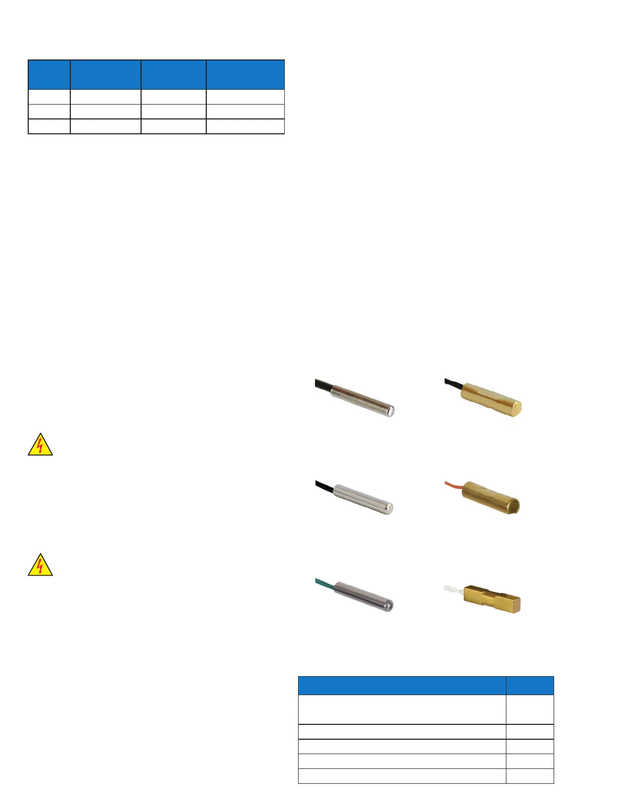
3. Set tt4P, Temperature Sensor Type. Select 2K, 3K, 10K
or 98.6K; see pictures below. Default is 2K.
4. Set Pt4P, Pressure Sensor Type. Select Absolute or
Gauge (sealed), following the steps above. Default is
Gauge.
5. Set Un_t, Temperature Units. Select Fahrenheit or
Celsius. Default is Fahrenheit.
6. Set Un_p, Pressure Units. Select PSI or Bar. Default is
PSI.
Setup is now complete. The Superheat Control will begin
controlling superheat, and will display SvpH. The controller
is now in the Process Values Menu (Appendix B). Rotate the
SELECT knob to view the values.
Table 2 - Electric Expansion Valves
SPORLAN MODEL NUMBERS STEPS
SEI-.5, SEI-1, SER-1.5, SEI-2, SEI-3.5, SEI-6,
SER-6, SEI-11, SER-11, SER-20
1596
SER-AA, A, B, C, D, F, G, J, K, L 2500
SEI-30 3193
SEI-50, SEH-100, SEH-175 6386
ESX, OEV, SEV, SEV-C and CEV 500
3K Surface Sensor
2K Air, Surface
or Well Sensor
10K Air Sensor
(Green or Yellow)
3K Air Sensor
(Black)
10K Surface Sensor
(Blue, Orange, or Red)
98.6K Surface Sensor
 Loading...