12
www.teejet.com
844-E Sprayer Control
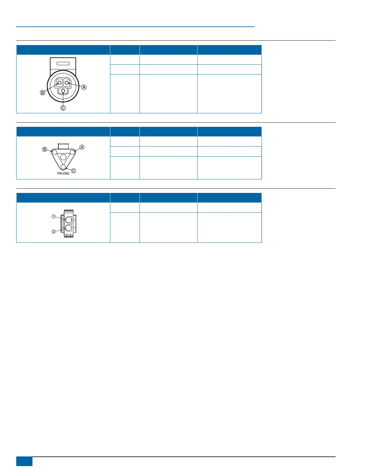
Figure 18: Pressure Sensor Connector
Pressure Sensor Connector Pin No. Wire Color Signal Name
A White Power Out
B Black Pressure Signal
C N/C
Figure 19: Flow Sensor Connector
Flow Sensor Connector Pin No. Wire Color Signal Name
A Brown Power Out
B White Flow Signal
C Green Sensor Ground
Figure 20: Regulator Connector
Regulator Connector Pin No. Wire Color Signal Name
1 White Regulation Valve (+)
2 Brown Regulation Valve (-)
NOTE: The 844 is designed to handle a maximum of 4 amps per boom section.
You are now ready to begin the programming of the TeeJet 844 Sprayer Control.
NOTE: Valves requiring DPDT switches are not compatible with the TeeJet 844 Sprayer Control.