Do you have a question about the Spraying Systems Co TeeJet 845 and is the answer not in the manual?
Details TeeJet Technologies' copyright and usage restrictions.
Lists other brand and product names as trademarks.
Outlines warranty disclaimers and liability limits.
Defines symbols used for DANGER, WARNING, CAUTION, and NOTE.
Provides general safety guidelines and precautions for operation.
Advises on safe practices for hydraulic systems.
Guidelines for safe handling of agricultural chemicals.
Precautions for operating pressurised spray systems.
Safety measures for automated steering systems.
Ensures safe operation, maintenance, and service of equipment.
Instructions for safe routing and maintenance of cables and hoses.
Guidelines for cleaning and protecting the touch screen.
Emphasizes using only TeeJet recommended parts.
Steps to power on the 845 sprayer console.
Procedure for safely powering off the console.
Explains the automatic power down feature.
Instructions on how to enter System or User Program Menu.
How to navigate through program steps.
Methods to change values or reset options.
Procedure to save inputs and exit setup mode.
Determining the best location for the control console.
Steps for securely mounting the console.
Wiring the console to the 12-volt battery system.
Illustrates the system's wiring connections.
Connecting main cable to master valve, boom valves, etc.
Determining optimal cable routing for sprayer components.
Warning about mounting components away from vibration.
Details pin assignments for the console connector.
Pinout for the power connector.
Details pin assignments for the speed sensor connector.
Pin assignments for the pressure sensor connector.
Details pin assignments for the flow sensor connector.
Pinout and function of the regulator connector.
Lists available options in System Setup Mode.
Instructions for navigating and operating the setup menu.
Procedures for backing up and restoring system configurations.
Selecting measurement units for operation.
Resetting system parameters to default values.
Calibrating the speed sensor for accurate readings.
Using the distance counter for measurement.
Configuring whether a pressure sensor is installed.
Calibrating the zero pressure reference for the sensor.
Steps for performing automatic calibration.
Configuring maximum/minimum pressure ratings.
Configuring flow meter installation and calibration.
Detailed steps for automatic flow meter calibration.
Inputting the actual volume sprayed for calibration.
Setting minimum flow capacity for the flow sensor.
Choosing between flow or pressure for regulation.
Setting the physical spacing between tips/nozzles.
Configuring the number of sprayer boom sections.
Setting the number of tips/nozzles per section.
Adjusting density for fertilizer application.
Selecting the type of regulating valve plumbing.
Adjusting regulating valve response speed.
Selecting the type of section control valves.
Setting the maximum tank size.
Setting the minimum tank level for alarms.
Choosing communication types (GPS, VR, etc.).
Using external GNSS receiver for speed data.
Using prescription data for variable rate application.
Enabling or disabling external GNSS speed input.
Using external rate data from a prescription map.
Verifying console functions without moving the sprayer.
Setting low and high speeds for simulation.
Setting minimum speed to shut off boom sections.
Lists parameters for OEM manufacturer setup.
Lists available options for application-specific setup.
Instructions for navigating application setup.
Setting the desired application rate.
Calculating speed based on rate and pressure.
Calculating pressure based on rate and speed.
Setting reference flow for programmable tips.
Selecting predefined tip/nozzle types and capacities.
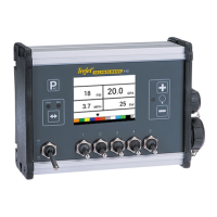
Description of the console's main work screen elements.
Steps to check sprayer and console connections before use.
Steps to initiate and manage the spraying process.
Control of individual boom sections.
Viewing and setting the current tank level.
Resetting total area, volume, and distance counters.
How simulated speed is deactivated.
Switching between manual and automatic regulation.
Increasing/decreasing application rate by 10% increments.
Adjusting the target application rate by 10% steps.
Resets the target application rate to the set rate.
Interpreting the LED indicator for regulation status.
Console powers off after inactivity to save battery.
Automatic switching between flow and pressure regulation.
Alarm for high difference between target and actual rate.
Alarms for no speed or low speed conditions.
Alarm triggered by no flow pulses.
Alarms for no pressure or low pressure conditions.
Warns of pressure differences in regulation.
Warns of flow differences in regulation.
Low priority alarm for tank level dropping below minimum.
Table for noting user settings in System Setup.
Table for noting user settings in OEM Menu.
Table for noting user settings in Application Setup.
| Brand | Spraying Systems Co |
|---|---|
| Model | TeeJet 845 |
| Category | Control Systems |
| Language | English |