24
www.teejet.com
INSTALLATION APPLICATION SETUPSYSTEM SETUP APPENDIXINTRODUCTION
845 Sprayer Control System
OPERATION
THE SPRAYING OPERATION
1. Switch the console on by pressing the PROGRAM button
on the display panel.
2. Toggle the boom switches to their “ON” position, for each of the
booms on your sprayer.
• Take note of the “numbered” booms on each side of the
sprayer, so that the appropriate boom can be toggled “OFF”
as necessary.
3. The AUTO/MANUAL button should be switched to “AUTO.”
• In the AUTO mode, when the Master Switch is “OFF”, the
target application rate as well as the target symbol will be
displayed in the console display. When the Master Switch is
“ON”, the actual rate will be displayed and the target symbol
will no longer appear.
Upon entering the eld at the point where spraying will begin, turn
the Master Switch to “ON” position. This will activate the spraying
operation. Maintain the usual vehicle speed for spraying. Moderate
changes in vehicle speed will not affect the application rate,
because such changes are compensated by automatic pressure
increases or decreases. If for any reason there is a need to stop,
turn the Master Switch to “OFF.”
Alarm warnings can occur momentarily while the pressure
regulating valve is searching for a new setting after the closing of a
boom section or other change in normal operation. However, if the
alarm stays on for a longer time, the valve may have reached its
limit and the system will be unable to regulate ow beyond the limit.
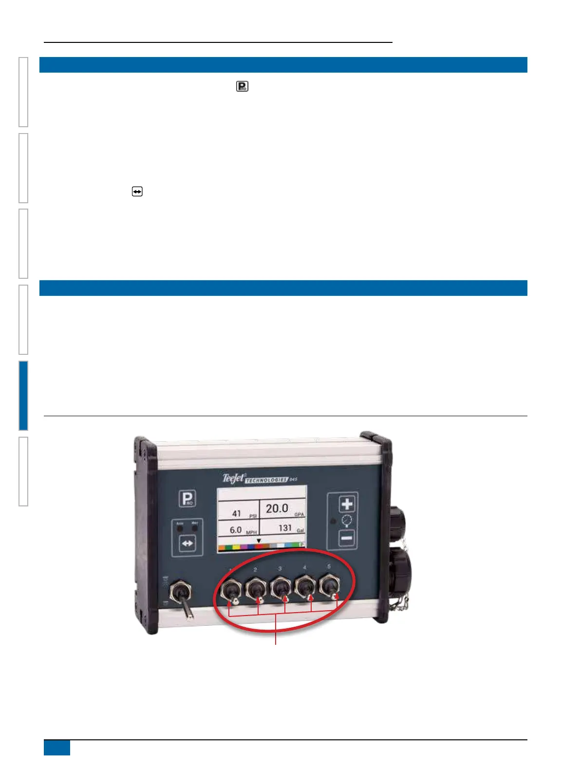
BOOM SECTIONS & SWITCHES
The console operates with, nine (9), seven (7), ve (5) or (3) three section switches (depending on console model) and one (1) Master
switch. Each section switch is associated with the same number of sections on the boom.
►Switches – control individual boom sections
◄On – Flip the switch up
◄Off – Flip the switch down
►Master switch – opens/closes the main product valves and enables/disables power to individual boom section on/off switches
Figure 5-2: Master Switch, 5 Section Switches
Boom Section Controls