5
98-70006-ENUS R4
844-E Sprayer Control
INSTALLING THE SPEED SENSOR ASSEMBLY
Components
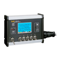
Two (2) magnets, Sensor with attached connector cable, and mounting
hardware. If you are installing a radar ground speed sensor, follow the
instructions supplied with that unit.
Speed Step 1 - Location
The speed sensor assembly should be installed on a non-driven wheel
to avoid potential errors that are likely to occur from a slipping drive
wheel. Refer to Figure 5.
Proximity Sensor (optional)
An optional proximity sensor is available to use in cases where space
is limited or for drive shaft mounting.
The proximity sensor will work by sensing any metal object. The
proximity sensor must be mounted so that the sensor face is within 1/8″
to 3/8″ (3-10 mm) of the metal object being read.
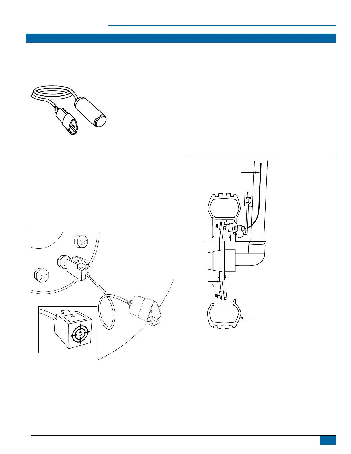
Figure 5: Wheel Mounting of Speed Sensor
NOTE:
TARGET FACES
Note: Target faces tire lugs
Figure 6: Wheel Mounting of Magnetic Speed Sensor
CABLE
MAGNET
RIM
SENSOR
TIRE