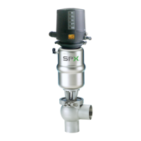
piston rod
seal screw
actuator
air connection
v-seal
o-ring
seal screw
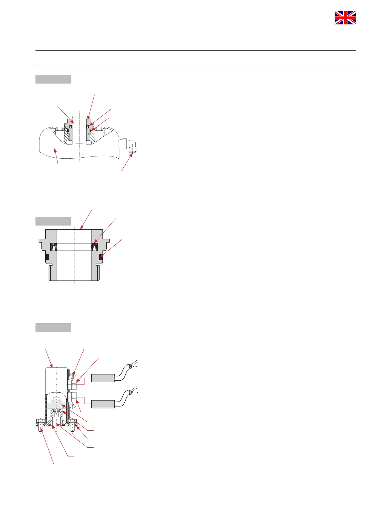
prox. switch holder
screw
guide rod
piston rod - actuator
actuator screw
housing
positioning screw
o-ring
hex. screw M8
centering washer
fig. 12.2.
fig. 12.3.
fig. 12.1.
v-seal
o-ring
18
APV_SW4_UK-4_082017.indd
UK
Single seat and change-over valve
DELTA SW4
Instruction manual: UK - rev.4
APV
12. Service Instructions for Actuator
12.1. Maintenance of actuator
1. Remove the air hoses from the actuator.
2. Remove the inner hexagon screws from the adapter of the
control unit.
3. Unscrew the two seal screws with a spanner SW30
while holding up the actuator with a strap wrench.
12.2. Installation of seals and assembly of actuator
1. Install the greased o-rings and v-seals in the seal screws (fig. 12.2).
See to the correct installing direction of the v-seal.
2. Slide the seal screws over the piston rod at both sides of the
actuator and tighten them.
3. Fasten the adapter for the control unit and the yoke on the actuator.
Attention: Observe position of the adapter.
Attention: Consider the required valve design
NC or NO during the installation of the yoke.
NC = normally closed / air-to-raise, spring-to-lower
NO = normally open / air-to-lower, spring-to-raise
4. Fasten the air hoses.
12.3. Actuator with valve position indicator
Assembly of holders (fig. 12.3.)
1. Install the actuator screw on the actuator.
2. Provide the housing with the o-ring.
3. Fasten the housing by means of the
3. Fasten the housing by means of the 4 hex. screws M8
on the actuator.
4. Release the screws at the proximity switch holder and insert
the corresponding proximity switches. Then fasten the screws.
5. Place the actuator in one limit position.
6. Place the corresponding proximity switch in the corresponding
position. Release the positioning screw and move the holder until
the corresponding signal is indicated. Then continue the movement
by 2 to 3 mm to secure indication.
Fasten the positioning screw.
7. Place the actuator in the other limit position and carry out
positioning of the second proximity switch.
 Loading...