© SPX FLOW, Inc.
Form No. 1000623
Rev. 6 Jan. 10, 2017
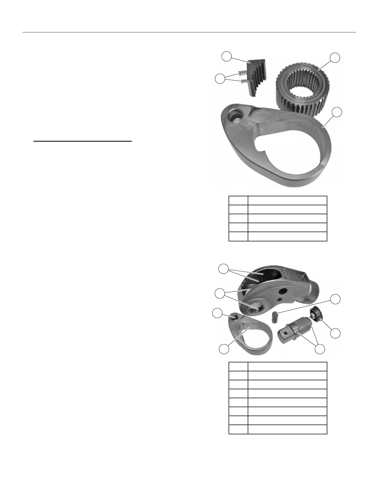
7. See Figure 9. Remove the ratchet, drive shoe and
springs from the crank.
8. Thoroughly clean all components, removing the old
lubricant using a mild degreasing agent. Inspect all
components for damage and/or excessive wear.
Inspect the ratchet and drive shoe teeth for damage,
cracks, etc. Any substandard component must be
replaced immediately using genuine parts supplied
by SPX Bolting Systems.
Drive Component Assembly
See Figure 10. Before assembly, apply a liberal coat of
Revol R5 Moly Anti Seize to the following areas:
• Body internal sideplates (where the crank
contacts).
• Crank bearings.
• Crank pocket where the drive shoe is located
(not the crank bore).
• Body sideplate journals.
• Square drive bearings.
• Square drive cap bearing.
IMPORTANT: Do not apply lubricant to the ratchet
and drive shoe teeth.
The hydraulic torque wrench drive components must
be lubricated using the specied product only. Using
alternative lubricants will affect the output and possibly
lead to premature component failure.
1. Place the drive shoe and springs into the crank
pocket and install the ratchet ensuring the springs
do not tilt. Verify that the ratchet teeth are driving in
the correct direction and are engaged with the drive
shoe teeth. Rotate the ratchet to ensure correct
operation.
2. Install the drive assembly into the wrench body,
centralise the crank pin hole in the body plug hole
and install the crank pin.
3. Press the drive assembly downwards to centralise
the ratchet in the sideplate journals.
4. Slide the square drive into the wrench body and
attach the square drive cap.
5. Install both body plugs
6. Ret the guard.
Repair Procedures continued
1
2
3
4
Item Description
1 Springs
2 Drive Shoe
3 Ratchet
4 Crank
Figure 9. Drive Disassembly
1
2
3
5
7
6
4
Item Description
1 Body Internal Sideplates
2 Crank Pin
3 Square Drive Cap Bearing
4 Square Drive Bearings
5 Crank Pocket
6 Crank Bearings
7 Sideplate Journals
Figure 10. Lubrication Areas