Maintenance Waukesha Cherry-Burrell Brand W60/W80 Valves
Page 36 95-03022 08/2018
W65/W85 Valve Assembly
Air-to-Raise Actuator
1. Screw the adapter (Figure 25, item 3) onto the yoke.
2. Install the upper body o-ring (item 6) onto the adapter.
3. Using 5/8-inch torque wrench flats on the stem, install the
upper valve stem (item 7a). Torque to 380 in/lbs.
4. Apply air to Port A to raise the stem.
5. Assemble the upper body to the adapter; secure it with the
upper body clamp (item 5).
6. Install the middle body o-ring (item 6) onto the upper body.
7. Assemble the middle body; secure it with the middle body
clamp (item 5).
8. Release the air pressure.
9. Using 5/8-inch torque wrench flats on the stem in the yoke
area, install the lower valve stem (item 7b) onto the upper
stem (item 7a). Torque to 380 in/lbs.
10. Install the lower body o-ring (item 6) on the middle body.
11. Assemble the lower body; secure it with the lower body clamp
(item 5).
12. Install the body o-ring (item 6) onto the bearing carrier and
insert it into the lower body.
13. Install the bearing carrier clamp (item 5).
Air-to-Lower Actuator
1. Screw the adapter (Figure 25, item 3) onto the yoke.
2. Install the upper body o-ring (item 6) onto the adapter.
3. Using 5/8-inch torque wrench flats on the stem, install the
upper valve stem (item 7a). Torque to 380 in/lbs.
4. Assemble the upper body to the adapter; secure it with the
upper body clamp (item 5).
5. Install the middle body o-ring (item 6) onto the upper body.
6. Assemble the middle body; secure it with the middle body
clamp (item 5).
7. Apply air to Port B to lower the stem.
8. Install the o-ring (item 9) in the counter bore of the lower stem
(item 7b).
9. Using 5/8-inch torque wrench flats on the stem in the yoke
area, install the lower valve stem (item 7b). Torque to 380 in/
lbs.
10. Install the lower body o-ring (item 6) on the middle body.
11. Assemble the lower body; secure it with the lower body clamp
(item 5).
12. Release the air pressure.
13. Install the body o-ring (item 6) onto the bearing carrier (item
11) and insert it into the lower body.
14. Install the bearing carrier clamp (item 5).
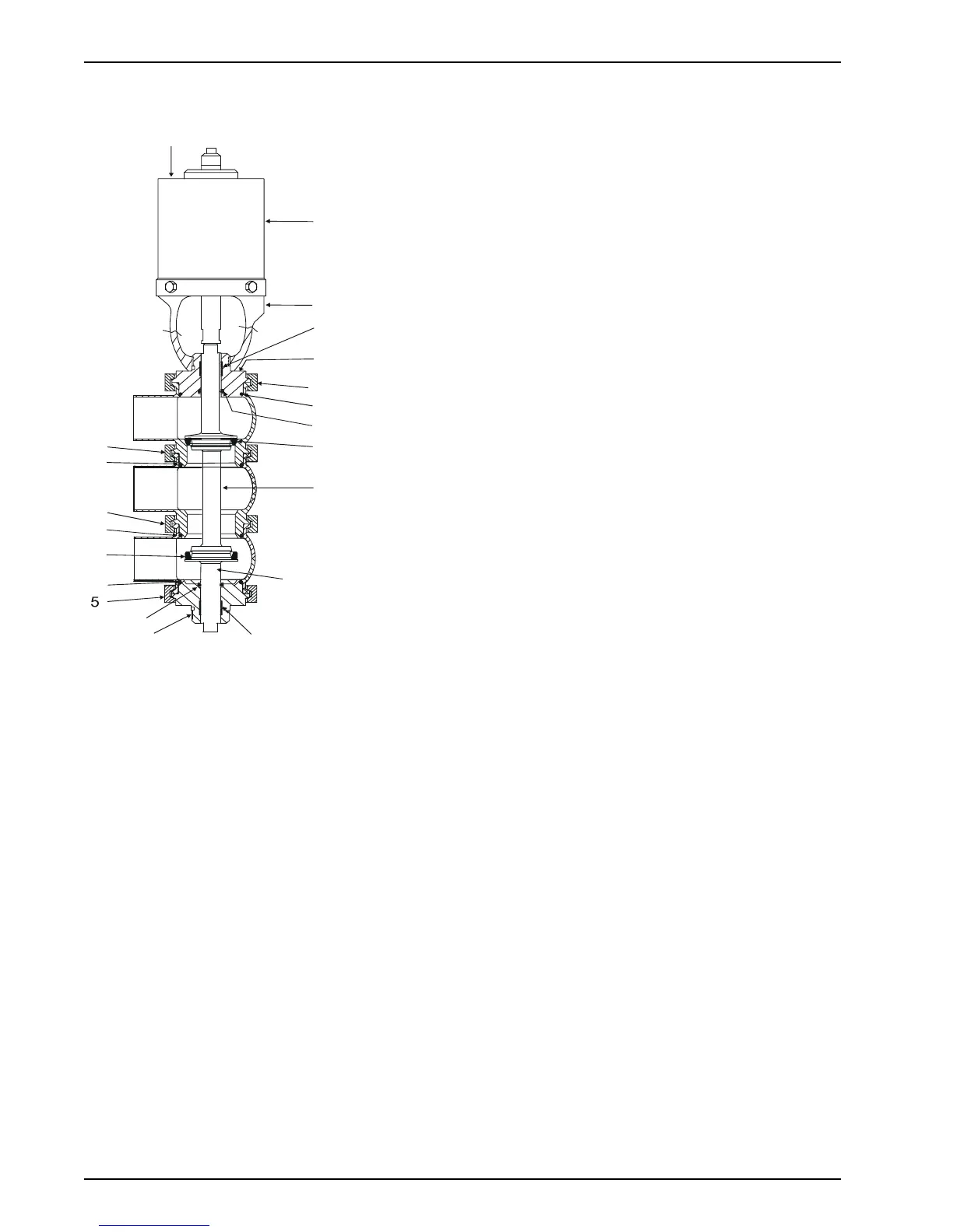
Figure 27: W65/W85 Divert Valve
VA100-245b
3,3a,
3b,3d
6
5
6
6
5
8
4