7
4.0 Operation
4.1 Start-up
A. During the initial start-up, slowly pressurize dryer to full
line pressure and check entire system for leaks. Depres-
surize and correct any leaks.
B. Energize the Dryer On-Off switch located on the enclo-
sure cover (Power-on light should illuminate).
NOTE: If dryer is installed with either internally or externally
mounted air by-pass valve, make certain that by-pass valve is
closed to prevent untreated air from flowing downstream.
4.2 Inlet, Purge, and Outlet Flows @ 100 psig
(7 kgf/cm
2
)
A. Inlet Flows
1. Maximum Inlet Flow at Rated Conditions
For maximum inlet flow at rated conditions refer to
Table 1.
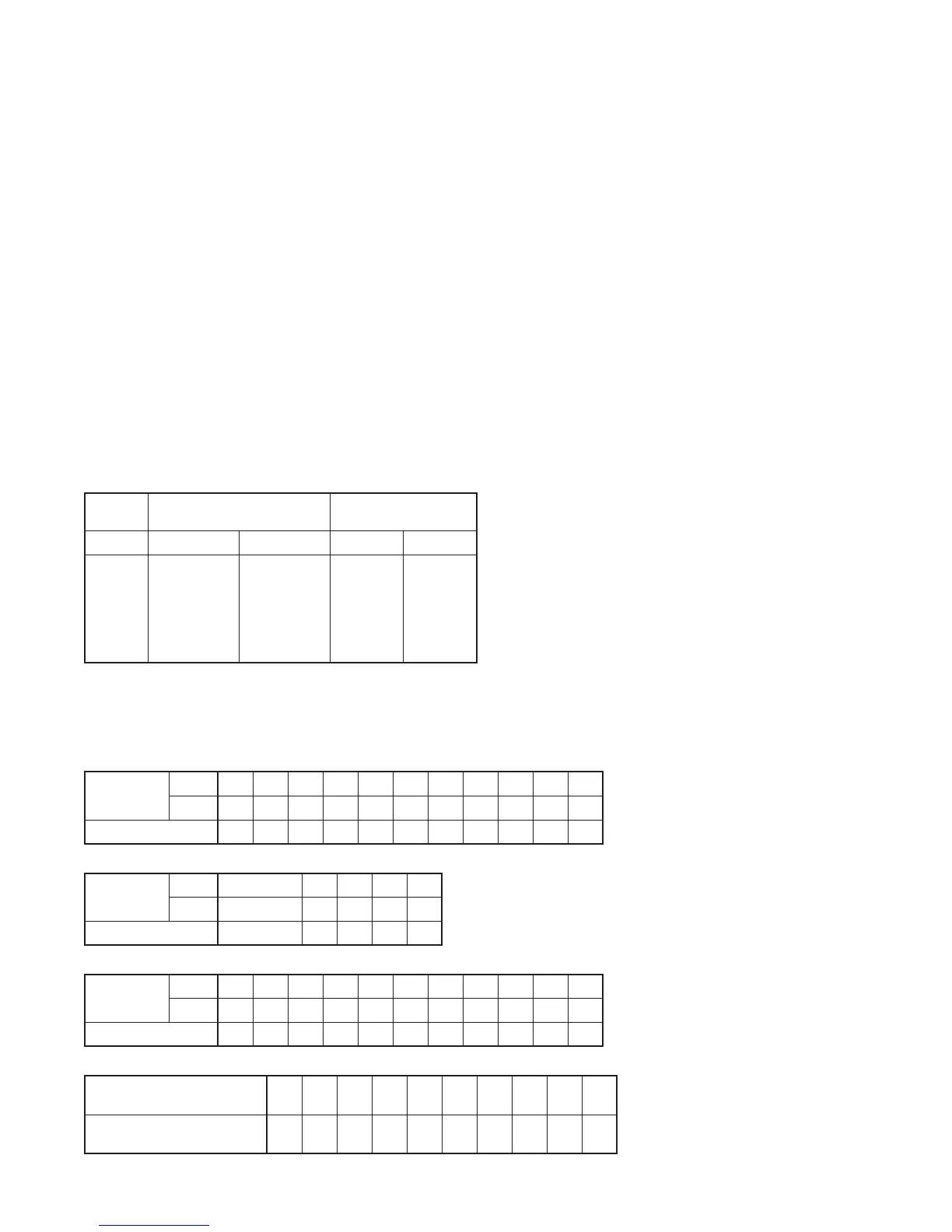
TABLE 1 Inlet and Purge Flows @ 100 psig
MODEL INLET FLOW (1)
scfm (m
3
/h)
PURGE FLOW (2)
scfm (m
3
/h)
-40°F (-40°C) -100°F (-73°C) Average Maximum
7
13
20
25
30
35
50
7.3 (12)
13 (22)
20 (34)
25 (42)
30 (51)
35 (59)
50 (85)
5.6 (9.5)
10 (17)
16 (27)
20 (34)
24 (41)
28 (48)
40 (68)
1.5 (2.5)
2.7 (4.6)
4.2 (7.1)
5.1 (8.7)
6.2 (11)
7.2 (12)
10.2 (17)
2.0 (3.4)
3.7 (6.3)
5.5 (9.3)
6.8 (12)
8.2 (14)
9.6 (16)
13.6 (23)
1. Inlet flows are established in accordance with CAGI (Compressed Air and Gas Institute) standard ADF-200,
Dual Stage Regenerative Desiccant Compressed Air Dryers - Methods for Testing and Rating. Conditions
for rating dryers are: inlet pressure - 100 psig (7 kgf/cm
2
); inlet temperature - saturated at 100°F (38°C).
2. Average Purge Flow is the total amount of air used to purge and repressurize off-stream towers averaged
over the cycle time. Maximum Purge Flow is the flow rate through the off-stream tower during that portion
of the cycle the purge/repressurization valve is open.
TABLE 2 Capacity Correction Factor for various inlet pressures
INLET
PRESSURE
psig 50 60 70 80 90 100 110 120 130 140 150
kgf/cm
2
3.5 4.2 4.9 5.6 6.3 7.0 7.7 8.4 9.1 9.8 10.5
Multiplier 0.31 0.42 0.54 0.73 0.83 1.00 1.09 1.17 1.26 1.35 1.44
TABLE 3 Capacity Correction Factor for various inlet temperatures
INLET
TEMPERATURE
°F 100 and below 105 110 115 120
°C 38 and below 41 43 46 49
Multiplier 1.00 0.98 0.96 0.93 0.89
TABLE 4 Purge Flow Correction Factor for various inlet pressures
INLET
PRESSURE
psig 50 60 70 80 90 100 110 120 130 140 150
kgf/cm
2
3.5 4.2 4.9 5.6 6.3 7.0 7.7 8.4 9.1 9.8 10.5
Multiplier 0.55 0.64 0.73 0.82 0.91 1.00 1.09 1.17 1.26 1.35 1.44
TABLE 5 Outlet pressure dew points at Moisture Indicator color change
INLET TEMP. °F
(°C)
35
(2)
40
(4)
50
(10)
60
(16)
70
(21)
80
(27)
90
(32)
100
(38)
110
(43)
120
(49)
OUTLET P.D.P. °F
(°C)
-34
(-37)
-28
(-33)
-22
(-30)
-16
(-27)
-10
(-23)
-4
(-20)
3
(-16)
9
(-13)
15
(-9)
21
(-6)
2. Maximum inlet flow at various pressures
To determine maximum inlet flow at inlet pressures
other than 100 psig (7kgf/cm
2
), multiply inlet flow
from Table 1 by multiplier from Table 2 that corre-
sponds to system pressure at inlet of dryer.
3. Maximum inlet flow at various temperatures
To determine maximum inlet flow at inlet tempera-
tures other than 100°F (38°C), multiply inlet flow from
Table 1 by multiplier from Table 3 that corresponds to
system temperature at inlet of dryer.
B. Purge Flow
For maximum and average purge flows at 100 psig
(7 kgf/cm
2
) refer to Table 1.
1. Maximum Purge Flow
Maximum Purge Flow (MFP) is the amount of purge
flowing through the off-stream tower when the
purge/repressurization valve is open. After the purge/
repressurization valve closes, the purge flow will
gradually decrease as the off-stream tower repres-
surizes to line pressure. Refer to Table 1 for Maximum
Purge Flows at 100 psig (7kgf/cm
2
).
 Loading...