10
© SPX
Form No. 1000572
Rev. 0 February 8, 2012
Initial Setup continued
AMPS
at Maximum
Hyd. Pressure
Electrical Cord Size AWG (mm
2
) 3.2 Volt Drop
Length of Electrical Cord
mm
2
AWG
0-8 m 8-15 m 15-30 m 30-46 m 0-25 ft 25-50 ft 50-100 ft 100-150 ft
6 0.75 1 1.5 2.5 18 16 14 12
10 0.75 1.5 2.5 4 18 14 12 10
14 1 2.5 4 6 16 12 10 8
18 1.5 2.5 6 6 14 12 8 8
22 1.5 4 6 10 14 10 8 6
26 2.5 4 6 10 12 10 8 6
30 2.5 4 10 16 12 10 6 4
Table 2. Minimum Recommended Gauge Table
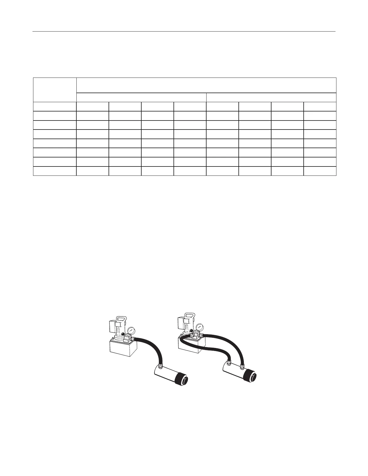
Bleeding Air from the System
Air can accumulate in the hydraulic system during the initial set-up or after prolonged use causing the
cylinder to respond slowly or in an unstable manner. To remove the air:
1. Open the ller plug two full turns.
2. See Figure 2. Place the cylinder at a lower level than the pump.
3. Extend and retract the cylinder several times without putting a load on the system. Air will be released
through the pump reservoir.
4. Cycle the hydraulic system until operation is smooth and consistent.
5. Check the pump reservoir level. Add Power Team hydraulic uid as needed.
Figure 2. System Bleeding
IMPORTANT: Some spring return cylinders or rams have a cavity in the rod which forms an air pocket.
This type of cylinder or ram should be bled when positioned upside down or lying on its side with the port
facing upward.
3. Start the pump and shift as required.
4. Turn off the pump when not in use.
 Loading...