9
© SPX
Form No. 1000572
Rev. 0 February 8, 2012
Initial Setup
1. Remove all packing materials from the assembled unit.
2. Inspect the unit upon arrival. The carrier, not the manufacturer, is responsible for any damage
resulting from shipment.
Filling the Pump Reservoir
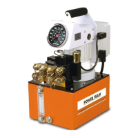
Most pumps are shipped without hydraulic uid in the reservoir. Hydraulic uid may have been shipped
in a separate container, but if hydraulic uid is needed, use only approved Power Team hydraulic uid
rated at AW 46 47 cSt @ 38°C (237 SUS @ 100°F). If low temperature requirements are needed, use
hydraulic uid 5.1 cSt @ 100°C (451 cSt @ -40°C).
1. Clean the area around the filler cap to remove debris. Debris in the hydraulic fluid can damage the
polished surfaces and precision-fit components of this pump.
2. Remove the filler cap and insert a clean funnel with a filter.
3. Fill the reservoir with hydraulic fluid to 1.3 cm (0.5 in.) from the cover plate.
4. Replace the filler cap. Verify the breather-hole is open, if applicable.
Hydraulic Connections
1. Clean the areas around the fluid ports of the pump and cylinders.
2. Inspect all threads and fittings for signs of wear or damage, replace as needed.
3. Clean all hose ends, couplers or union ends.
4. Remove the thread protectors from the hydraulic fluid outlets.
5. Connect the hose assembly to the hydraulic fluid outlet, and couple the hose to the cylinder.
CAUTION: To prevent personal injury from leaking hydraulic uid, seal all hydraulic
connections with a high-quality, non-hardening, pipe thread sealant.
IMPORTANT: Sealant tape or non hardening sealer tape can be used to seal hydraulic
connections if only one layer of tape is used. Apply tape carefully, two threads back, to
prevent it from being pinched by the coupler and broken off inside the system. Loose
pieces of sealant could travel through the system and obstruct the ow of uid or cause
jamming of precision-t parts.
Electric Motor Operation
The electric motor is wired for nominal 115 or nominal 230 volts, 50/60 Hz. Some motors can be
rewired. Consult Power Team technical support.
1. Verify the hydraulic valve is in the neutral or hold position.
2. Connect the motor to a power supply.
Caution:
• The correct voltage is required for the pump to operate. Verify the voltage rating on the pump
motor name plate matches the outlet or power source you are using. Low voltage may cause:
an overheated motor; a motor that fails to start under load; motor surging when trying to
start; or a stalled motor before maximum pressure is reached.
• Check the voltage at the motor with the pump running at full pressure.
• Never run the motor on long, light gauge extension cords. Refer to Table 2. Minimum
Recommended Gauge Table.

 Loading...


