M
Melissa MorrisonAug 15, 2025
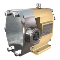
Why SPX Water Pump has no flow and is not priming?
- MMatthew DelgadoAug 15, 2025
The SPX Water Pump might not be priming due to several reasons. The suction lift may be too high, so you should reduce the difference between the pump and suction tank level, increase the suction pipe diameter, or reduce the length and simplify the suction pipe. There could be an air leak in the suction line that needs repair. If the viscosity is very low, increase the pump speed and reduce axial clearance. Also, check if the suction strainer or filter is clogged and clear it if necessary. Ensure the pump casing is correctly installed. Finally, verify the motor's rotation direction, changing connections for 3-phase drivers or swapping the suction and discharge openings, while checking the safety relief valve location.