29
© SPX
Form No. 1000528
Rev. 1 December 2, 2011
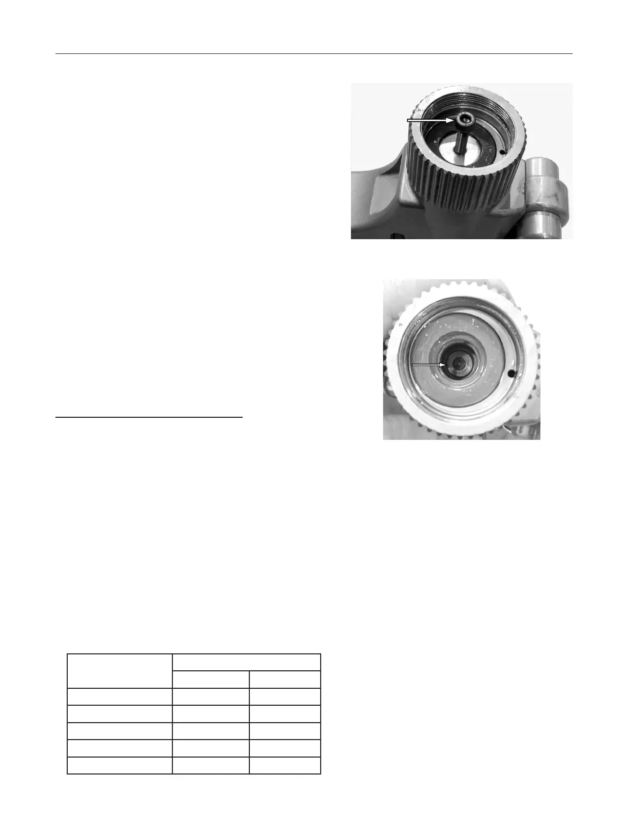
See Figure 23. Remove the piston plug from the 5.
end of the piston by screwing an M6 or M8 screw
(depending on the wrench model) into the hole in
the back of the piston plug, and pulling to remove.
See Figure 24. Remove the shoulder screw from 6.
inside the piston.
It is now possible to withdraw the piston from the 7.
cylinder. It may be necessary to temporarily re-install
the piston plug and circlip back into the piston and
use an M6 or M8 bolt to withdraw the piston in the
same manner used to withdraw the piston plug.
Remove and discard the piston seal and rod seal 8.
located in the center of the body.
NOTE: Access to the rod seal will be easier
if the drive components are either pushed
forward or removed.
Clean and inspect the piston and cylinder bore for 9.
scoring, pitting, and damage that could impair the
sealing ability, and replace/repair as necessary.
Inspect the endcap threads for damage.10.
Hydraulic Cylinder/Body Assembly
Note: All seals should be new and lubricated
with clean hydraulic oil or seal assembly paste
before installation.
Assemble a new rod seal into the body. Assemble a 1.
new piston seal onto the piston, and verify that the
seal backup rings' joints are rotated 180° apart.
With the seals and bores coated in clean hydraulic 2.
oil, insert the piston into the body cylinder bore.
Take care not to damage the seals or dislodge the
backup rings as the piston enters the bore.
Apply one drop of low-strength thread-locking 3.
adhesive to the threads of the shoulder screw, slide
it through the piston, and screw it into the shuttle.
Tighten the shoulder screw in accordance with the
following torque specications.
Wrench Size Torque
Nm in-lb
TWSD1 20 178
TWSD3 20 178
TWSD6 30 266
TWSD11 30 266
TWSD25 50 443
Repair Procedures continued
Figure 23. Piston Plug Removal
Figure 24. Shoulder Screw Removal
 Loading...