27
© SPX
Form No. 1000528
Rev. 1 December 2, 2011
See Figure 19. Lift out the multiswivel post. Remove 7.
and discard the port seals and post seals.
Clean and inspect all components including the
hydraulic couplings. If the hydraulic couplings are
damaged, remove and replace (multiswivel yoke
threads are 1/4-in. NPT). Inspect the components for
scoring, pitting, and damage, which could impair the
sealing ability, and replace as necessary.
Multiswivel Manifold Assembly
NOTE: All seals should be new and lubricated
with clean hydraulic oil or seal assembly paste
before installation.
Install the new o-ring seals into the base of the 1.
multiswivel post.
Attach the multiswivel post to the hydraulic torque 2.
wrench body using the four off screws. Apply a drop
of low-strength thread-locking adhesive, and torque
the screws to 3.5 Nm (31 in-lb).
Assemble three new o-ring seals to the multiswivel 3.
post.
Assemble four new o-ring seals to the multiswivel 4.
banjo.
Carefully push the banjo onto the post, ensuring the 5.
seals do not get damaged.
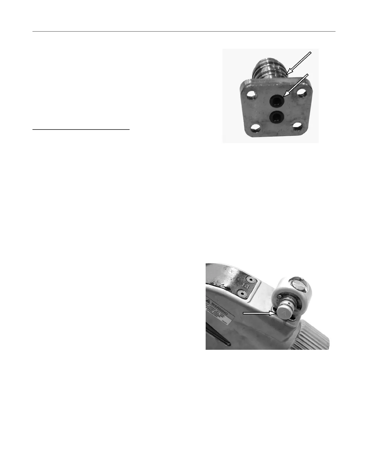
See Figure 20. Attach the banjo circlip to the post.6.
Assemble the advance and retract yokes to the 7.
banjo.
IMPORTANT: Be sure to install the advance and
retract yokes onto the banjo correctly. The banjo is
hard stamped with A (advance) and R (retract) to in-
dicate the correct position of the associated yoke.
Reversal of the yokes will cause the torque wrench
to malfunction and can lead to damage.
Rotate the yokes around the banjo until the yoke 8.
keyways engage.
Clamp the advance and retract yokes together by 9.
installing the yoke screw and torquing to 5 Nm (44
in-lb).
Check the operation of the multiswivel manifold by 10.
rotating and tilting. Movement should be smooth
and free.
Repair Procedures continued
Figure 19. Multiswivel Post
Removal
Figure 20. Circlip Installation
 Loading...