© 2013–2017 Schneider Electric All Rights Reserved
I-Line™ Combo Switchboards 80043-808-02 Rev. 02
Installation—Interior Mounting into Square D Brand Enclosures 03/2017
14
ENGLISH
I-Line Circuit Breaker Removal
Refer to Figure 3, I-Line Circuit Breaker Installation and Removal,
on page 13 for the following instructions.
1. Turn OFF all power to the I-Line Combo switchboard.
2. Turn the circuit breaker OFF.
3. Remove the I-Line interior trim cover (see Figure 2, Interior Trim
Removal, on page 12).
4. Remove the load wire. Secure the wire and cover the
exposed end.
5. Loosen the retaining screw(s) (C) in the circuit breaker mounting bracket
until the screw(s) is completely removed from the 7/32 in. (5.6 mm)
mounting hole in the mounting pan.
6. Place the screwdriver through the rectangular hole in the circuit
breaker mounting bracket and into the screwdriver slot in the
mounting pan. Ratchet the circuit breaker away from the bus bar
stack.
7. Lift the circuit breaker away from the bus bars.
8. Install the blank fillers where the circuit breaker was removed (refer to
Table 1, Blank Extensions and Blank Fillers Catalog Numbers,
on page 21, for reference).
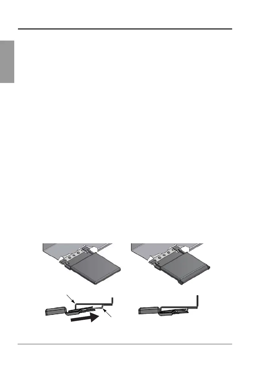
9. Secure the blank filler extensions to the I-Line section trim cover
(refer to Table 1, on page 21, for reference). Mount the extension on
the mounting bracket in the I-Line section trim cover as shown
in Figure 4.
10. Reinstall the I-Line interior trim cover (Figure 2, on page 12).
11. Re-energize the I-Line Combo switchboard.
Figure 4: Blank Filler Extension Installation
Blank filler extension
HLW4BL
Blank filler extension
HLW4EBL
I-Line section
trim cover
Mounting bracket
80043-808-01.book Page 14 Wednesday, March 22, 2017 12:31 PM
 Loading...