EasyManua.ls Logo

Srne ASF4880S180-H - User Manual

Srne ASF4880S180-H
41 pages
Print Icon
To Next Page IconTo Next Page
Loading...
V2.1
USER MANUAL
ASF4880S180-H
ASF48100S200-H
All-in-one solar charge inverter

Questions and Answers

  • A
    Andrea PriceAug 14, 2025
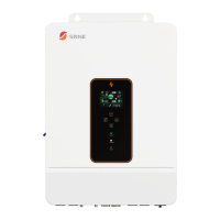
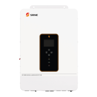
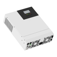
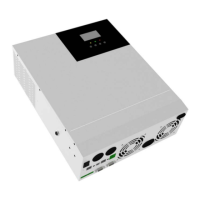
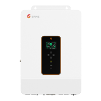
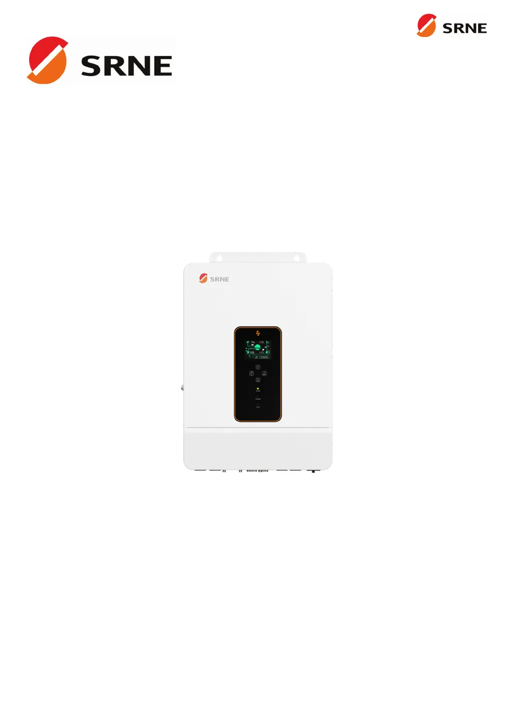
    How to fix Srne ASF4880S180-H screen with no display?
    • D
      danielle82Aug 14, 2025
      If your Srne Inverter screen isn't displaying anything, it could be due to no power input or the device being in sleep mode. First, ensure the circuit breaker is closed and the rocker switch is turned ON. If it's in sleep mode, push any button on the panel to wake it up.
  • M
    Michael PerryAug 17, 2025
    What to do if the Srne ASF4880S180-H Inverter says the battery is not connected?
    • N
      Nathaniel AcostaAug 17, 2025
      If your Srne Inverter indicates that the battery is not connected, there are a few things to check: * Ensure the battery is reliably connected. * Verify that the battery's circuit breaker is closed. * If you're using a Li-ion battery, make sure its BMS (Battery Management System) is communicating properly.
  • N
    Nicole StoneAug 20, 2025
    What causes bypass overload on a Srne Inverter and how to fix it?
    • J
      Joseph MarksAug 21, 2025
      A bypass overload on your Srne Inverter, detected by software, typically occurs when the bypass output power or current is too high for an extended period. To resolve this, reduce the load power being drawn and then restart the device. More details can be found in item 11 of the protection features.
  • H
    hannahadamsAug 25, 2025
    Why is my Srne ASF4880S180-H showing a battery under-voltage error?
    • A
      alexanderjohnAug 25, 2025
      The battery under-voltage error on your Srne Inverter means the battery voltage is lower than the value set in parameter [14]. To fix this, charge the battery until its voltage is higher than the value specified in parameter [14].
  • A
    alan50Aug 27, 2025
    What to do if Srne ASF4880S180-H Inverter shows battery over-discharge?
    • H
      Henry FordAug 27, 2025
      If your Srne Inverter is showing a battery over-discharge, it means the battery voltage is lower than the value set in parameter [12]. You can manually reset it by powering off and restarting the inverter. Alternatively, it will automatically reset once you charge the battery to a voltage higher than the value set in parameter [35].
  • E
    eric44Aug 30, 2025
    Why is my Srne ASF4880S180-H Inverter showing a battery over-voltage error during charging?
    • T
      tristanwalkerAug 30, 2025
      If your Srne Inverter displays a battery over-voltage error during charging, it indicates that the battery voltage is too high. You should manually power off and restart the inverter. Check if the battery voltage exceeds the limit. If it does, discharge the battery until the voltage is below the battery's over-voltage recovery point.
  • G
    griffintaylorSep 2, 2025
    How to resolve a utility input phase fault on a Srne ASF4880S180-H Inverter?
    • T
      Tanya WilliamsSep 3, 2025
      A utility input phase fault on your Srne Inverter indicates that the AC input phase doesn't match the AC output phase. To correct this, ensure that the phase of the AC input is the same as the phase of the AC output. For example, if the output is in split-phase mode, the input must also be in split-phase.
  • B
    Brenda NelsonSep 6, 2025
    What to do when Srne Inverter reports a fan failure?
    • D
      davidknightSep 6, 2025
      If your Srne Inverter reports a fan failure, which is detected by hardware for 3 seconds, manually toggle the fan after switching off the device. Check the fan for any blockage by foreign objects.
  • J
    James MaciasSep 9, 2025
    What should I do if my Srne ASF4880S180-H Inverter shows an AC input relay short-circuit error?
    • W
      William LopezSep 9, 2025
      If your Srne Inverter indicates an AC input relay short-circuit, which suggests the relay for AC input is sticking, manually power off and restart the device. If the fault reappears after restarting, you need to contact the after-sales service to repair the machine.

Summary

Safety Information

How to Use This Manual

Explains how to use the user manual for product operation and maintenance.

Symbols in This Manual

Details the meaning of symbols used in the manual for warnings and notices.

Essential Safety Instructions

Provides crucial safety instructions regarding high voltage and proper inverter handling.

Production Instructions

Product Introduction

Introduces the ASF series inverter and its advanced control algorithm.

Product Features

Lists the key features of the ASF series inverter, including battery support and communication.

System Connection Diagram

Illustrates the typical system components and connection scenario for the inverter.

Production Overview

Details the physical layout and component identification of the inverter unit.

Installation Guide

Select Mounting Location

Provides guidelines for choosing a suitable indoor mounting location for the inverter.

Mounting the Inverter

Explains the procedure for physically mounting the inverter onto a wall using specified hardware.

Terminal Cover Removal

Instructs on how to safely remove the terminal protection cover for access.

Connection Procedures

Single-Phase Output

Describes the single-phase AC output characteristics and voltage configuration options.

Single-Phase System Mode

Illustrates the system wiring for single-phase operation including PV, utility, and battery.

Cable and Circuit Breaker Requirements

Specifies the required cable diameters and circuit breaker ratings for PV, AC, and battery connections.

Cable Preparation Guidance

Provides guidance on preparing cables with ferrules and lugs for secure connections.

AC Input and Output Connection

Details how to connect the AC input and output wires according to terminal layout.

Battery Connection

Explains the correct procedure for connecting the positive and negative battery cables.

PV Connection

Describes how to connect the positive and negative wires for the PV strings.

Dry Contact Connection

Explains how to connect communication cables to the dry junction port.

Grounding Connection

Emphasizes the importance of correctly connecting the grounding terminal to the grounding bar.

Final Assembly Steps

Instructs to reinstall the terminal protection cover after wiring is confirmed.

Inverter Startup Procedure

Outlines the step-by-step procedure for safely powering up the inverter.

Inverter Operation

Operation and Display Panel

Introduces the inverter's LCD screen, indicators, and touchable keys.

Touchable Keys Overview

Details the function of each touchable key for navigating menus and settings.

LED Indicators

Explains the meaning and color coding of the AC/INV, CHARGE, and FAULT LED indicators.

Display Panel Icons

Provides a detailed breakdown of icons and their meanings displayed on the inverter screen.

Icon Explanations

Lists and defines various icons used to represent inverter status and functions.

View Real-Time Data

Guides users on how to access and interpret real-time operating data displayed on the inverter.

Inverter Settings

Parameter ID and Options

Explains the concept of Parameter ID and illustrates the layout for viewing and modifying settings.

Setting Parameters (ID 00-11)

Details parameters related to AC output, battery charging, and battery type settings.

Setting Parameters (ID 12-23)

Lists parameters for battery protection, equalization, and power saving modes.

Setting Parameters (ID 24-38)

Covers parameters for over-temperature restart, buzzer alarms, communication, and output functions.

Setting Parameters (ID 39-61)

Details parameters for charge current limits, time-slot charging/discharging, and SOC settings.

Setting Parameters (ID 62-63)

Explains parameters for switching to inverter SOC and N-PE bonding.

AC Output Modes

Utility Priority Output

Explains the utility-first AC output mode prioritizing utility power.

Solar and Utility Hybrid Output

Describes the hybrid output mode balancing solar and utility power.

Solar Priority Output

Details the solar-first AC output mode maximizing solar energy usage.

Inverter Priority Output

Explains the inverter-priority mode using solar and battery power.

Battery Charging Modes

Hybrid Charging

Describes hybrid charging prioritizing solar, supplementing with utility.

Utility Priority Charging

Explains utility-priority charging for the battery when solar is unavailable.

Solar Priority Charging

Details solar-priority charging, using utility when solar fails.

Only Solar Charging

Describes solar-only charging as an energy-efficient method.

Time-Slot Charging;Discharging

Peak-Valley Electricity Tariff

Illustrates a typical tariff structure to guide time-slot settings.

Utility Charging;Carrying Time Slots

Explains setting time periods for utility charging and load carrying.

Battery Discharging Time Slots

Details setting time periods for battery discharge to power loads.

Battery Parameters

Lead-acid Battery Parameters

Lists battery parameters for Sealed, Gel, and Flooded lead-acid types.

Li-ion Battery Parameters

Lists battery parameters for Ternary, LFP, and User-defined Li-ion types.

Communication Interfaces

Communication Overview

Provides an overview of the communication ports available on the inverter.

USB-B Port Usage

Explains the use of the USB-B port for connecting to host software for parameter management.

RS485-1 Port

Details the RS485-1 port for connecting to Wi-Fi/GPRS modules for mobile app access.

CAN;RS485-2 Port

Explains the CAN/RS485-2 port for BMS communication with Li-ion batteries.

Dry Contact Functions

Describes the functions of the dry contact port, including remote control and sampling.

Fault and Remedy

Fault Code Reference

Lists fault codes, their meanings, and instructions for troubleshooting.

Fault Code Listings

Continues listing fault codes, meanings, and instructions for inverter issues.

Troubleshooting Guide

Provides troubleshooting steps based on fault codes and their causes.

Fault Code Listings

Lists remaining fault codes, causes, and remedies for inverter operational issues.

Protection and Maintenance

Protection Features

Details various protection features implemented in the inverter for safety and longevity.

Protection Feature Details

Continues listing protection features and their corresponding instructions and operations.

Maintenance Recommendations

Provides recommendations for regular maintenance to ensure optimal inverter performance.

Technical Datasheet

Model Specifications

Presents technical specifications for the ASF4880S180-H and ASF48100S200-H models.

General and Communication Specs

Provides general physical, environmental, and communication specifications.

Certifications

Lists the safety, EMC, and RoHS certifications obtained by the inverter.

Srne ASF4880S180-H Specifications

General IconGeneral
ModelASF4880S180-H
Rated Power8000W
Max. PV Array Power9000W
Max. Input Current18A
AC Voltage230V
AC Frequency50/60Hz
Battery Voltage48V
Output Voltage230V
Frequency50/60Hz
Efficiency93%
Max. DC Voltage500V
MPPT Voltage Range120-450V
Output Power8000W
Peak Power16000VA
Protection FeaturesOverload, Short Circuit, Over Temperature

Related product manuals