2322
www.sunnyrooproducts.com
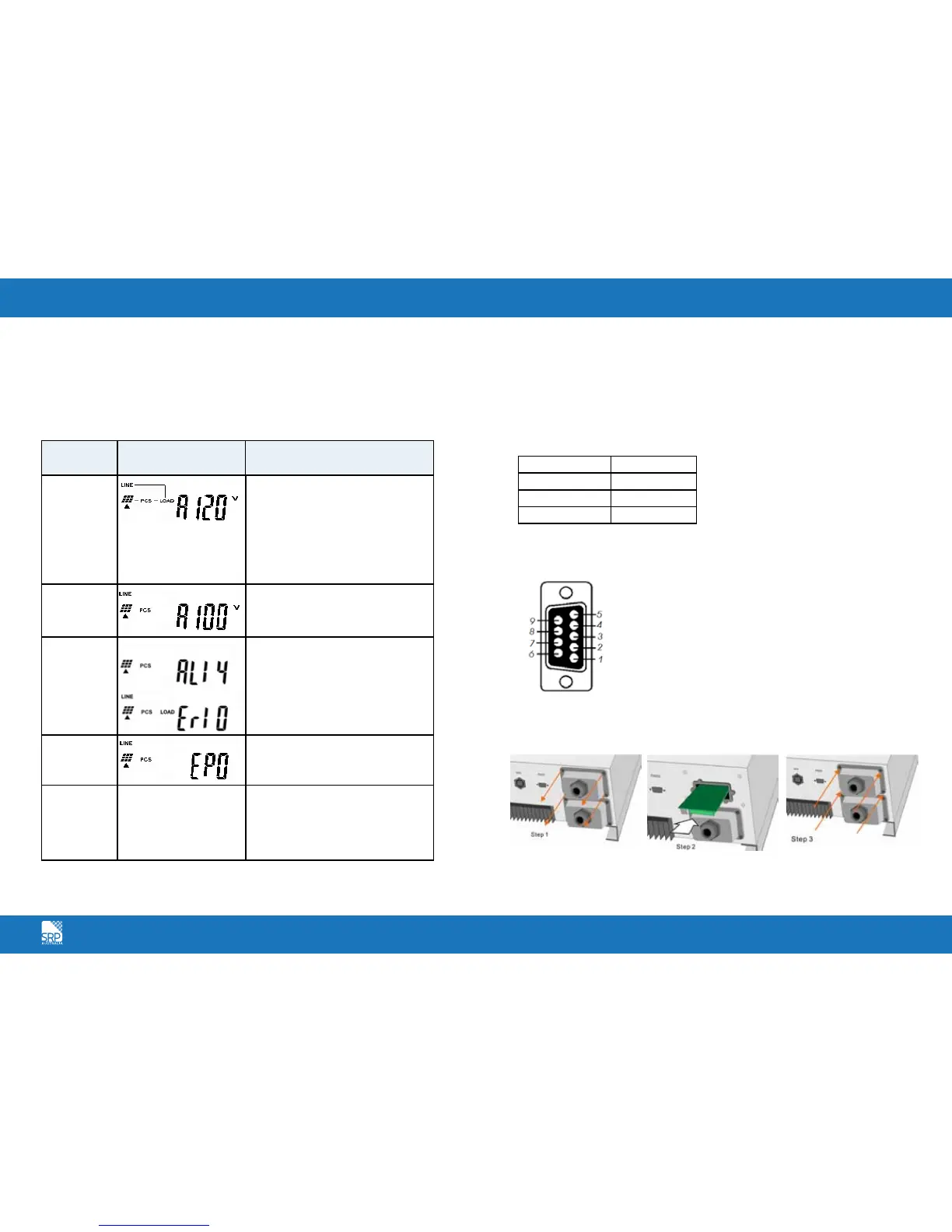
SR Series Inverter Status Descriptions
The SR Series Inverter starts up automatically when DC-power from the PV
panel is sufficient. Once the inverter starts, it enters into one of the following
status:
The Communications Interface
Standard communications interface
RS232 interface definition
The RS232 interface shall be set as follows:
Baud Rate 9600 bps
Data Length 8 bits
Stop Bit 1 bit
Parity None
The Pin Assignments of true RS232 type. The pin assignments of true RS232
type are illustrated as follows:
Optional Communication Card
Hardware Installation Procedure
Operation
mode
LCD panel display Description
Normal
In this mode, the SR Series Inverter
works normally. Whenever the
supplied power from PV panel is
sufficient (500VDC>PV>120VDC), the
SR Series Inverter converts power to
the grid as generated by the PV panel.
In normal mode, the green LED is on
to indicate that power is being fed to
the grid.
Standby
If the power is insufficient,
(60VDC<PV<120VDC) the SR Series
Inverter enters into a standby mode
but will attempt to connect to the grid.
Error
The internal intelligent controller can
continuously monitor and adjust the
system status. If the SR Series Inverter
finds any unexpected conditions such
as grid problems or internal failure, it
will display the information on its LCD
and light up the red LED.
EPO
Emergency Power Off Mode. In this
mode, the SR Series Inverter does not
take any power from the grid.
Shutdown
In case of little or no sunlight, the SR
Series Inverter automatically stops
running. In this mode, the SR Series
Inverter does not take any power from
the grid. The display and all of the
LEDs on the front panel do not work.
Pin 2: RS232 Rx
Pin 3: RS232 Tx
Pin 5: Earth
Open the top and sides
of the cabinet
Put the communication
card into the slot
Screw back the side and
top cover and complete
the installation