1716
www.sunnyrooproducts.com
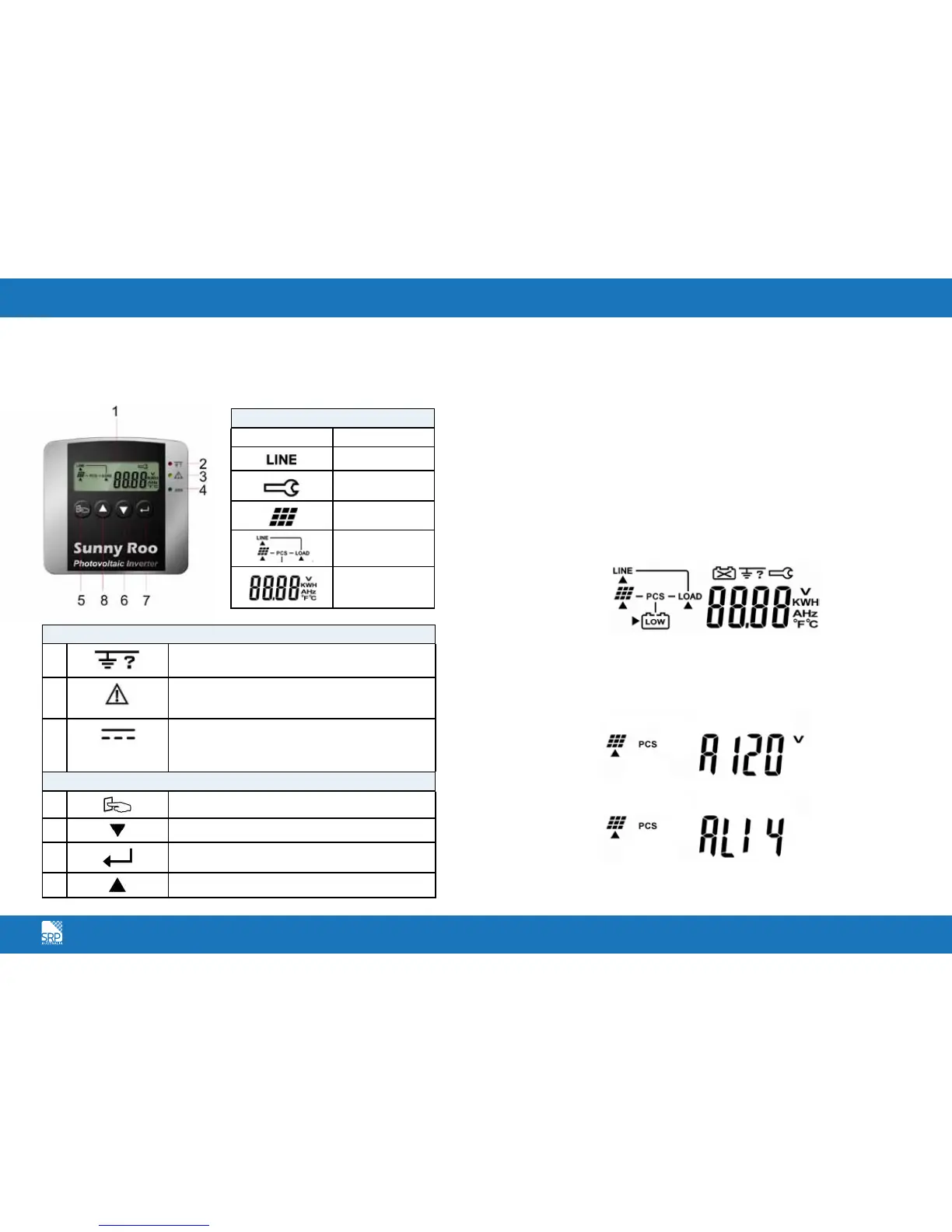
Front Panel Functional Descriptions
Symbols on the LCD Display Panel
Starting the SR Series Inverter
Before the inverter is started, check the following:
The housing cover is securely screwed tight.
The AC breaker is OFF.
The DC cables (PV strings) are fully connected.
The AC (utility) cable is connected correctly.
Operation Test and Installation Instruction
Connect the PV string voltage by switching on the DC circuit breaker. The
SR Series Inverter starts automatically when it receives DC voltage greater than
120Vdc. All of the LEDs will light up. The LCD display will illustrate drawing A.
After 3 seconds, the LCD display will illustrate from drawing A to drawing B1
and B2. The Green LED flashes to indicate that the DC input power is smaller
than sleep power. The yellow LED steadily lights up to indicate that no utility
exists.
LCD Display
Symbol Description
Utility Source
Inverter working
in specified mode
Solar Cell
Inverter operation
mode Flow Chart
4 Digits
Measurement
Display
LED Indicators
2
RED LED steadily lights up to indicate an Earth
fault or a DC input isolation fault.
3
YELLOW LED steadily lights up to indicate that the
utility (ex. voltage, frequency etc.) does not match
the input standard of the inverter.
4
Green LED steadily lights up to indicate that the
Solar Cell power is greater than sleep power; the
LED flashes to indicate that the Solar Cell power is
smaller than sleep power.
Control Keypads
5
Special Function Log in /out.
6
Go to next page.
7
To re-confirm the change of Inverter Setting.
8
Go to previous page.
A.
B1.
B2.