EasyManua.ls Logo

ST MB1367 User Manual

ST MB1367
43 pages
To Next Page IconTo Next Page
Page #1 background imageLoading...
Page #1 background image
Introduction
The STM32G4 Nucleo-64 boards based on the MB1367 reference board (NUCLEO-G431RB, NUCLEO-G474RE, NUCLEO-
G491RE) provide an affordable and flexible way for users to try out new concepts and build prototypes with the STM32G4
Series microcontrollers, choosing from the various combinations of performance, power consumption and features. The
ARDUINO
®
Uno V3 connectivity and the ST morpho headers provide an easy means of expanding the functionality of the
Nucleo open development platform with a wide choice of specialized shields. The STM32G4 Nucleo-64 boards do not require
any separate probe as they integrate the STLINK-V3E debugger/programmer. The STM32G4 Nucleo-64 boards come with the
comprehensive free software libraries and examples available with the STM32CubeG4 MCU Package.
Figure 1. NUCLEO-G474RE top view
Figure 2. NUCLEO-G474RE bottom view
Pictures are not contractual.
STM32G4 Nucleo-64 boards (MB1367)
UM2505
User manual
UM2505 - Rev 3 - November 2020
For further information contact your local STMicroelectronics sales office.
www.st.com

Table of Contents

Question and Answer IconNeed help?

Do you have a question about the ST MB1367 and is the answer not in the manual?

ST MB1367 Specifications

General IconGeneral
ModelMB1367
Form FactorMicro ATX
Storage Interface4 x SATA 6Gb/s
USB Ports6 x USB 2.0
Video Outputs1 x HDMI
LANRealtek

Summary

Introduction

Features

Ordering information

Codification

Explains the meaning of the product codification for STM32G4 Nucleo-64 boards.

Development environment

System requirements

Details the operating systems and cables required for development.

Development toolchains

Lists the supported Integrated Development Environments (IDEs) for STM32G4.

Demonstration software

Information on preloaded demonstration software and its availability.

Conventions

Quick start

Getting started

Step-by-step guide to configure the board and launch the demonstration application.

Hardware layout and configuration

PCB layout

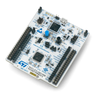
Detailed layout of the Printed Circuit Board (PCB) for the Nucleo-64 board.

Mechanical drawing

Provides mechanical dimensions of the STM32G4 Nucleo-64 board in millimeters.

Embedded STLINK-V3E

Details on the integrated STLINK-V3E debugger/programmer.

Power supply

Debugging while using VIN or EXT as an external power supply

Procedure for debugging when using external VIN or E5V power sources.

Clock sources

HSE clock (high-speed external clock)

Details on configuring the High-Speed External (HSE) clock source.

LSE clock (low-speed external clock) – 32.768 kHz

Details on configuring the Low-Speed External (LSE) clock source.

Board functions

LEDs

Description of the board LEDs (LD1, LD2, LD3, LD4) and their functions.

Push-buttons

Details on the user (B1) and reset (B2) push-buttons.

MCU voltage selection on VREF+

How to select the voltage source (VREF or VDD) for the MCU VREF+ pin.

Current consumption measurement (IDD)

Instructions for measuring microcontroller current consumption using jumper JP6.

Virtual COM port (VCP): LPUART and USART

Configuration for LPUART and USART interfaces for Virtual COM port functionality.

Solder bridges

Board connectors

STLINK-V3E USB Micro-B connector CN1

Details of the USB connector for STLINK-V3E programming and debugging.

MIPI10 connector CN4

Pinout and description of the MIPI10 connector for external debugging.

ARDUINO® Uno V3 connectors CN5, CN6 CN8 and CN9

Information on ARDUINO Uno V3 compatible connectors for shields.

ST morpho connectors CN7 and CN10

Details of ST morpho connectors for accessing MCU signals.

STM32G4 Nucleo-64 I/O assignment

STM32G4 Nucleo-64 board information

Product marking

Information on product identification markings on the PCB sticker.

Board revision history

Details of the document's revision history and changes.

Known limitations

Describes known issues with the board, specifically the OPAMP offset.

Federal Communications Commission (FCC) and ISED Canada Compliance Statements

Revision history

Related product manuals