Home
ST
Microcontrollers
STM32F0 Series
ST STM32F0 Series Application Note
5
of 1
of 1 rating
52 pages
Give review
Manual
Specs
To Next Page
To Next Page
To Previous Page
To Previous Page
Loading...
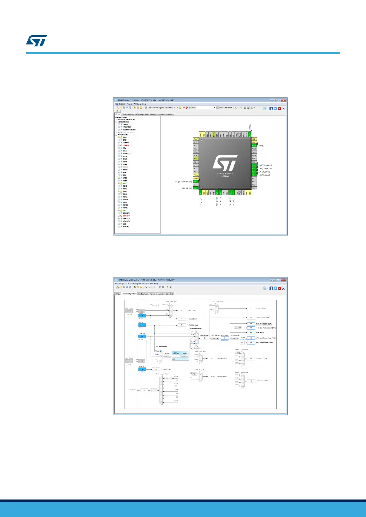
Figure 26
shows the results obtained.
Figure 26.
STM32F072B-DISCO pinout overview
7.2.3
STM32F072B-DISCO clock tree
It uses the default clock tree setting.
Figure 27.
STM32F072B-DISCO clock configuration
AN5105
Discovery board: STM32F072B-DISCO
AN5105
-
Rev 1
page 28/52
27
29
Table of Contents
1 General Information
2
2 Terminology and Principle
3
Terminology
3
Principle
3
Table 1. Change Transfer Principle Documentation
4
Figure 1. Change Transfer Principle
4
3 Document Reference
5
Table 2. References Documentation
5
Figure 2. Main Documentation Tree
5
4 STM32L4 Touch Sensing Controller Online Presentation
6
Figure 3. STM32L4 Online Training
6
Figure 4. STM32L4 Touch Sensing Controller Online Training
6
5 Main Characteristics
7
Description
7
Signal Threshold
7
Figure 5. TSC Characteristics
7
Table 3. Signal Threshold Usage Documentation
8
Figure 6. Stmstudio Outputs
8
Charge Transfer
9
Table 4. Charge Transfer Documentation
9
Figure 7. Incomplete and Complete Charge Transfert Cycle
9
Sensitivity
10
Table 5. Sensitivity Documentation
10
Table 6. Dielectric Constants of Common Materials Used in a Panel Construction
10
Sensor
11
Key
11
Table 7. Key Documentation
11
Figure 8. Sensor Size
11
Linear or Slider
12
Table 8. Linear Touch Sensor Documentation
12
Figure 9. Interlaced Linear Touch Sensor with 3 Channels / 4 Electrodes (Half-Ended Electrodes Design)
12
Rotary or Wheel
13
Table 9. Rotary Sensor Documentation
13
Figure 10. Interlaced Patterned Rotary Sensor with 3 Channels / 3 Electrodes
13
Active Shield or Driven Shield
14
Table 10. Active Shield Documentation
14
Figure 11. Active Shield Principle
14
Layout and PCB
15
Led Rules
15
Table 11. Led Rules Documentation
15
Figure 12. Led Layout Example
15
Figure 13. Example of Cases Where a LED Bypass Capacitor Is Required
15
Electrode Not Located on PCB
16
Table 12. Electrode Documentation
16
Figure 14. Electrode Not Located on PCB Example
16
Ground, Shield and Sensors
17
Table 13. Layout Documentation
17
Figure 15. Hatched Ground and Signal Tracks
17
Figure 16. Ground Plane Example
17
Figure 17. Track Routing
18
Figure 18. Track Routing Recommendation
18
Figure 19. Shield
19
Faq
20
Noise
21
Power Supply
21
False Detection
21
Table 14. Power Supply Documentation
21
Table 15. False Detection Documentation
21
Figure 20. Typical Power Supply Schematic
21
Noise Immunity
22
Conducted Noise
22
Table 16. Noise Immunity Documentation
22
Table 17. Conducted Noise Documentation
22
6 Tuning
23
Table 18. Sensors Documentation
23
Table 19. ESD Documentation
23
Table 20. Conducted Noise Documentation
23
Table 21. Sampling Capacitor Documentation
23
7 Getting Started TSC with Stm32Cubemx
24
Uses Cases
24
Figure 21. Main Project Panel
24
Discovery Board: STM32F072B-DISCO
25
STM32F072B-DISCO Board Selection
25
Figure 22. STM32F072B-DISCO Board Selection
25
Figure 23. STM32F072B-DISCO Board Schematics
25
TSC Group and Sensor Activation
27
Figure 24. STM32F072B-DISCO Pinout SWD
27
Figure 25. STM32F072B-DISCO Pinout TSC
27
STM32F072B-DISCO Clock Tree
28
Figure 26. STM32F072B-DISCO Pinout Overview
28
Figure 27. STM32F072B-DISCO Clock Configuration
28
STM32F072B-DISCO Touchsensing Library
29
Figure 28. TOUCHSENSING Box Configuration
29
Figure 29. STM32F072B-DISCO Sensor Selection
29
Figure 30. STM32F072B-DISCO Sensor Selection Step2
30
Figure 31. STM32F072B-DISCO Sensor Selection Step3
30
Figure 32. STM32F072B-DISCO Sensor Selection Step4
31
Figure 33. STM32F072B-DISCO Sensor Selection Step5
31
STM32F072B-DISCO Software Project Generation
32
Figure 34. STM32F072B-DISCO Software Generation Step1
32
Figure 35. STM32F072B-DISCO Software Generation Step2
32
Figure 36. STM32F072B-DISCO Software Generation Step3
33
Figure 37. STM32F072B-DISCO IDE Workspace
33
Software Basic Algorythm
34
Figure 38. STM32F072B-DISCO Setup
35
Discovery Board: STM32L0538-DISCO
36
STM32L0538-DISCO Board Selection
36
Figure 39. STM32L0538-DISCO Board Selection
36
Figure 40. STM32L0538-DISCO Board Schematics
37
STM32L0538-DISCO TSC Group and Sensor Activation
38
Figure 41. Pinout SWD
38
Figure 42. Pinout TSC
38
STM32L0538-DISCO Clock Tree
39
Figure 43. Pinout Overview
39
Figure 44. Clock Configuration
39
STM32L0538-DISCO Touchsensing Library
40
Figure 45. TOUCHSENSING Box Configuration
40
Figure 46. STM32L0538-DISCO Sensor Selection Step1
40
Figure 47. STM32L0538-DISCO Sensor Selection Step2
41
Figure 48. STM32L0538-DISCO Sensor Selection Step3
41
Figure 49. STM32L0538-DISCO Sensor Selection Step4
42
Figure 50. STM32L0538-DISCO Sensor Selection Step5
42
STM32L0538-DISCO Software Project Generation
43
Figure 51. STM32L0538-DISCO Software Generation Step1
43
Figure 52. STM32L0538-DISCO Software Generation Step2
43
STM32L0538-DISCO Software Basic Algorythm
45
Revision History
46
Table 22. Document Revision History
46
Other manuals for ST STM32F0 Series
Programming Manual
91 pages
5
Based on 1 rating
Ask a question
Give review
Questions and Answers:
Need help?
Do you have a question about the ST STM32F0 Series and is the answer not in the manual?
Ask a question
ST STM32F0 Series Specifications
General
Brand
ST
Model
STM32F0 Series
Category
Microcontrollers
Language
English
Related product manuals
ST STM32F2
1371 pages
ST STM32F030
40 pages
ST STM32F205
29 pages
ST STM32F101xx
1096 pages
ST STM32F7 Series
54 pages
ST STM32F40 Series
1422 pages
ST STM32F20 Series
29 pages
ST STM32F10 Series
519 pages
ST STM32F102 series
690 pages
ST STM32F103 series
14 pages
ST STM32F446 Series
1328 pages
ST STM32F207 series
1381 pages