5.6.3 Ground, shield and sensors
Table 13 gives a list of documents containing information about the layout .
Table 13. Layout documentation
Id Title Chapters
AN4312
Guidelines for designing touch sensing applications
with surface sensors
• PCB and Layout
• Ground considerations
• Rotary and linear sensor recommendations
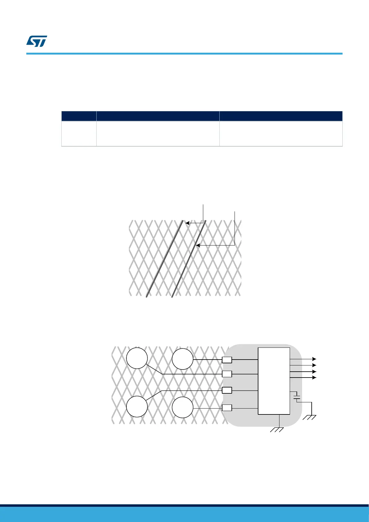
Figure 15 shows the ground plane and the signal tracks.
Figure 15. Hatched ground and signal tracks
Must be avoided
Track is OK
Figure 16. Ground plane example
GPIO1
Tkey1
Tkey2
Tkey4
Tkey3
Rx
Rx
Rx
Rx
GPIO2
GPIO3
GPIO4
C
S
Hatched ground plane (optional)
Flood ground plane (mandatory)
AN5105
Layout and PCB
AN5105 - Rev 1
page 17/52

 Loading...


