PM0075 Overview
Doc ID 17863 Rev 1 9/31
The Flash memory is organized as 32-bit wide memory cells that can be used for storing
both code and data constants. The Flash module is located at a specific base address in the
memory map of each STM32F10xxx microcontroller type. For the base address, please
refer to the related STM32F10xxx reference manual.
The information block is divided into two parts:
● System memory is used to boot the device in System memory boot mode. The area is
reserved for use by STMicroelectronics and contains the boot loader which is used to
reprogram the Flash memory using the USART1 serial interface. It is programmed by
ST when the device is manufactured, and protected against spurious write/erase
operations. For further details please refer to AN2606.
In connectivity line devices the boot loader can be activated through one of the
following interfaces: USART1, USART2 (remapped), CAN2 (remapped) or USB OTG
FS in Device mode (DFU: device firmware upgrade). The USART peripheral operates
with the internal 8 MHz oscillator (HSI). The CAN and USB OTG FS, however, can only
function if an external 8 MHz, 14.7456 MHz or 25 MHz clock (HSE) is present. For
further details, please refer to AN2662 (“STM32F105xx and STM32F107xx system
memory boot mode”) available from www.st.com.
● Option bytes
Write operations to the main memory block and the option bytes are managed by an
embedded Flash Program/Erase Controller (FPEC). The high voltage needed for
Program/Erase operations is internally generated.
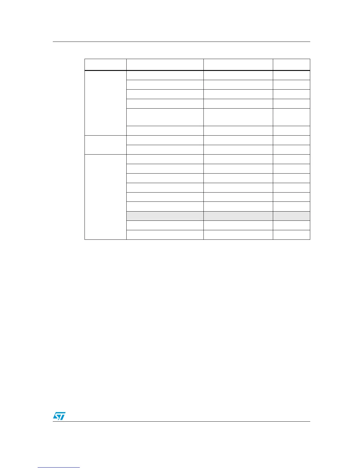
Table 4. Flash module organization (connectivity line devices)
Block Name Base addresses Size (bytes)
Main memory
Page 0 0x0800 0000 - 0x0800 07FF 2 Kbytes
Page 1 0x0800 0800 - 0x0800 0FFF 2 Kbytes
Page 2 0x0800 1000 - 0x0800 17FF 2 Kbytes
Page 3 0x0800 1800 - 0x0800 1FFF 2 Kbytes
.
.
.
.
.
.
.
.
.
Page 127 0x0803 F800 - 0x0803 FFFF 2 Kbytes
Information block
System memory 0x1FFF B000 - 0x1FFF F7FF 18 Kbytes
Option Bytes 0x1FFF F800 - 0x1FFF F80F 16
Flash memory
interface
registers
FLASH_ACR 0x4002 2000 - 0x4002 2003 4
FLASH_KEYR 0x4002 2004 - 0x4002 2007 4
FLASH_OPTKEYR 0x4002 2008 - 0x4002 200B 4
FLASH_SR 0x4002 200C - 0x4002 200F 4
FLASH_CR 0x4002 2010 - 0x4002 2013 4
FLASH_AR 0x4002 2014 - 0x4002 2017 4
Reserved 0x4002 2018 - 0x4002 201B 4
FLASH_OBR 0x4002 201C - 0x4002 201F 4
FLASH_WRPR 0x4002 2020 - 0x4002 2023 4
 Loading...