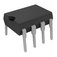
Figure 15 : Error Amp Configuration.
Z
i
Z
f
1mA
2
1
V
FB
COMP
2.5V
D95IN345
+
-
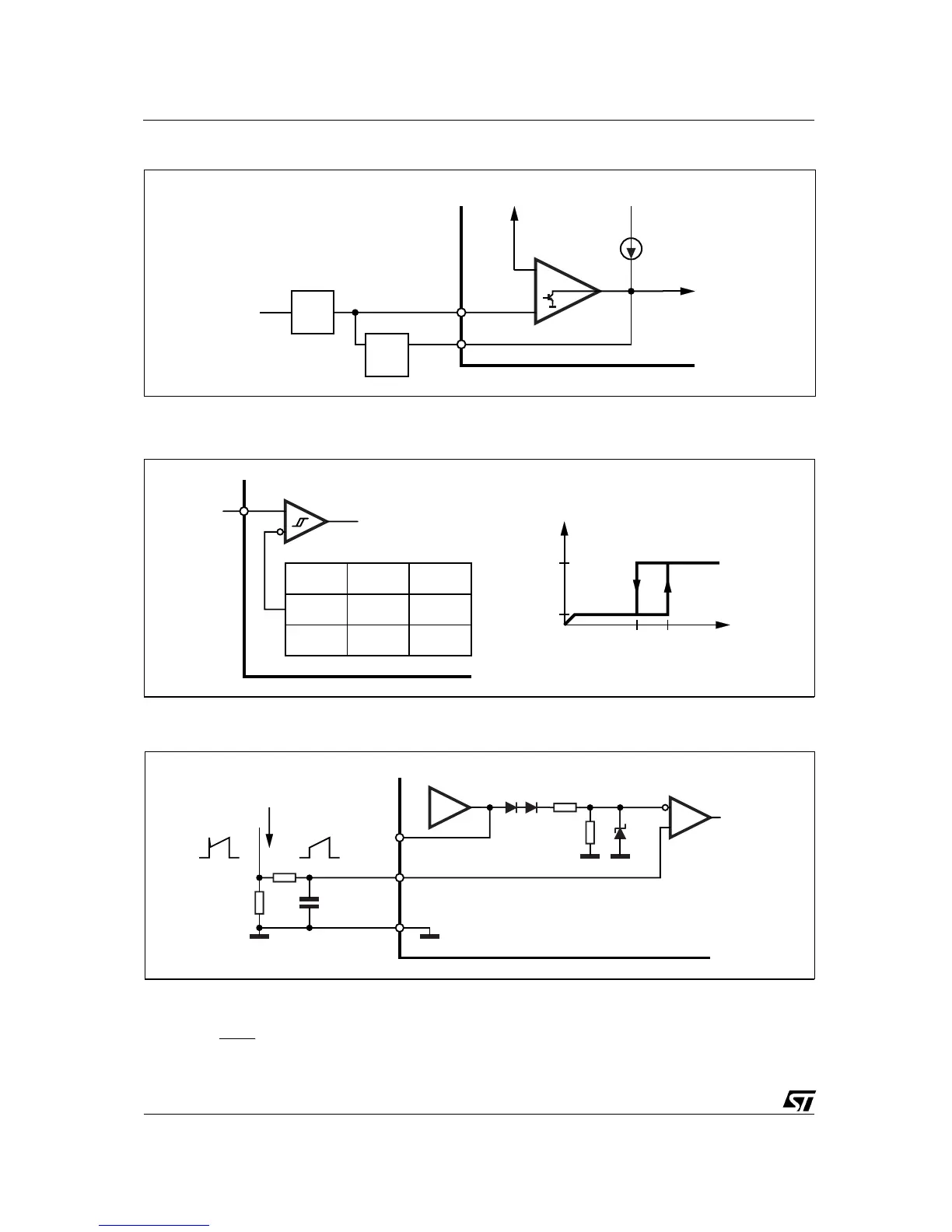
Figure 16 : Under Voltage Lockout.
UC3842B
UC3844B
UC3843B
UC3845B
16V 8.4V
10V 7.6V
V
ON
V
OFF
V
i
ON/OFF COMMAND
TO REST OF IC
7
<0.5mA
<17mA
I
CC
V
CC
V
OFF
V
ON
D95IN346
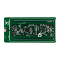
Figure 17 : Current Sense Circuit .
ERROR
AMPL.
2R
R1V
CURRENT
SENSE
COMPARATOR
1
CURRENT
SENSE
COMP
CR
S
R
3
5
GND
I
S
D95IN347
Peak current (i
s
) is determined by the formula
1.0 V
I
S max
≈
R
S
A small RC filter may be required to suppress switch transients.
During UVLO, the Output is low
UC2842B/3B/4B/5B - UC3842B/3B/4B/5B
8/15