EasyManua.ls Logo

ST STM8S - User Manual

ST STM8S
23 pages
Print Icon
To Next Page IconTo Next Page
Loading...
February 2010 Doc ID 15330 Rev 4 1/23
UM0671
User manual
STM8/128-EV/TS
STM8S touch sensing evaluation board
Introduction
The STM8S touch sensing evaluation kit (STM8/128-EV/TS) provides a platform that
introduces users to STMicroelectronics capacitive touch sensing firmware library.
The kit contains an STM8S touch sensing (TS) evaluation daughterboard (STM8Sxxx-TS1)
in addition to the STM8/128-EVAL board.
The STM8S touch sensing evaluation daughterboard provides an evaluation platform for
resistor-capacitor (RC) touch sensing technology for an implementation using 5 keys and
one slider.
The STM8S TS evaluation kit provides a software solution for transforming any 8-bit STM8
microcontroller (MCU) into a capacitive touchkey controller.
For further details about the touch sensing software library, please read the technical
documentation available on www.st.com/touch-sense-sw-lib.
Figure 1. STM8S touch sensing evaluation kit
www.st.com
Downloaded from Arrow.com.

Other manuals for ST STM8S

Question and Answer IconNeed help?

Do you have a question about the ST STM8S and is the answer not in the manual?

Summary

Introduction

Overview

Getting Started with the Touch Sensing Evaluation Kit

Evaluation Kit Contents

Lists the items included in the STM8S touch sensing evaluation kit.

Using the Evaluation Kit

Explains how to connect and use the evaluation kit for firmware evaluation.

User Interface

Describes the joystick and touch keys used for navigating the kit's menu.

Evaluation Kit Board Settings

STM8 S Touch Sensing Daughterboard

Overview of the STM8S touch sensing daughterboard and its components.

Dielectric

Describes the Plexiglas panel used as dielectric between electrodes and touch surface.

Daughterboard MCU Pin Functions

Details the application functions assigned to each pin of the daughterboard microcontroller.

Daughterboard Power Supply

Explains how the daughterboard is powered through the motherboard.

SWIM Connections

Describes the SWIM interface for debugging and programming.

Analysis Connectors (J2 and J3)

Details connectors J2 and J3 for analyzing electrode and shield signals.

External Supply and Communication

Describes connector J6 for I2C communication and external supply.

STM8 S2 xx Evaluation Motherboard Settings

Describes the necessary settings for the STM8S2xx evaluation motherboard.

Advanced Evaluation Using a Debugging Environment

Running Firmware in Debug Mode

Guides on running the evaluation firmware using ST debugging tools.

Entering Debug Mode Using RLink

Steps to set up a platform for evaluating and developing TS firmware with RLink.

Exploring Key Structures

Explains how to monitor touch sensing data structures in STVD watch window.

STM8 Sxxx-TS1 Daughterboard Schematics

Revision History

Overview

The STM8S touch sensing evaluation kit (STM8/128-EV/TS) serves as a platform for introducing users to STMicroelectronics' capacitive touch sensing firmware library. This kit is designed to facilitate the evaluation and development of touch-sensing applications using an 8-bit STM8 microcontroller (MCU).

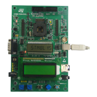
The kit comprises an STM8S touch sensing (TS) evaluation daughterboard (STM8Sxxx-TS1) and an STM8/128-EVAL motherboard. The daughterboard specifically provides an evaluation environment for resistor-capacitor (RC) touch sensing technology, featuring five keys and one slider for user interaction. The STM8S TS evaluation kit offers a comprehensive software solution that enables any 8-bit STM8 MCU to function as a capacitive touchkey controller. For in-depth information regarding the touch sensing software library, users are directed to the technical documentation available on the STMicroelectronics website.

Function Description

The primary function of the STM8S touch sensing evaluation kit is to enable designers to create advanced user interfaces by replacing traditional electro-mechanical switches with touch sensing controls. This solution allows for the integration of touch sensing capabilities with conventional MCU features such as communication, LED control, beeper, and LCD control. The touch sensing firmware library is an integral part of the application firmware, emphasizing maturity, robustness, flexibility, and performance. This makes the solution straightforward to implement, reducing the "time to market" for developing diverse applications, including mobile phones, cooking appliances, and printers.

The evaluation kit comes pre-programmed with firmware that manages the five touch keys and one slider on the daughterboard. This pre-loaded firmware allows users to quickly assess the software features and performance of the touch sensing library by monitoring sensing parameters via an LCD display interface.

In development mode, designers can debug, modify, adapt, or integrate the touch sensing library into their application firmware. This is supported by USB debugging and programming tools, including the Raisonance RLink debugger/programmer for ST microcontrollers, the STice in-circuit emulation system, and the ST MCU Toolset, which includes the ST Visual Develop (STVD) IDE and ST Visual Programmer (STVP) programming interface.

Usage Features

Upon connecting the motherboard to the mains supply, the evaluation kit is ready for use. Navigation through the menu options is primarily done using a joystick. The joystick allows users to display key values and states, and to modify key touch sensing library parameters such as de-bounce filter, detection time-out, low power mode, and DES settings. The five touch sensing keys on the daughterboard also serve as navigation controls within the touch sensing menu.

The display options accessible via the joystick include:

  • Displaying the state of keys (K1-K5) and the slider on a single screen.
  • Displaying only the state of a selected key (Idle or Detected).
  • Displaying the signal value and reference threshold of a selected key.
  • Displaying the number of samples rejected by the noise filtering system.
  • Displaying the state of the slider (Idle or Detected).
  • Displaying the signal value and position of the slider.
  • Displaying/changing slider resolution (default is 4 bits, adjustable up to 7 bits).

Parameter setting options, also navigated via the joystick, include:

  • Detection time-out: This feature automatically recalibrates keys after a fixed duration of continuous touch detection, preventing keys from becoming "stuck on" due to foreign objects or sudden influences. After recalibration, keys resume normal operation even if partially or fully obstructed. An infinite timeout (value = 0) is useful for applications requiring prolonged detection to be reflected in the output.
  • De-bounce filter: This filter mitigates the effects of low-frequency noise on key states. It requires a specified number of consecutive measurements to qualify as a detection, and similarly, the end of a touch must be confirmed over several measurements. The typical value is 2.
  • Low power mode: This feature reduces device power consumption by inserting a programmable low power mode window between each key acquisition period. Window durations can be set to 0, 1, 2, 4, 8, 16, 32, 64, or 128 milliseconds.
  • Detection Exclusion System (DES): DES prevents multiple keys from responding to a single touch, which can occur with closely spaced keys. Once a key is touched, all other keys are locked in an untouched state until the touched key returns to an untouched state.

The daughterboard features a 1.5-mm thick Plexiglas panel as a dielectric between the electrodes and the touch surface. This panel is interchangeable, allowing users to experiment with different dielectric materials or thicknesses. However, new firmware parameters will need to be tuned accordingly.

Maintenance Features

The STM8S touch sensing evaluation kit offers several features to aid in maintenance and development:

  • Analysis connectors (J2 and J3): These connectors provide access to all electrode and driven shield signals for analysis and monitoring. Users should be aware of potential probe capacitance disturbance and may need to recalibrate the device after connecting probes.
  • I2C communication connector (J6): This connector provides I2C data and clock signals for communication with the daughterboard microcontroller, enabling users to develop their own communication protocols. Resistors R36 and R37 are available as I2C pull-up resistors and can be mounted if needed.
  • SWIM connector and setting jumper (J5 and W1): A single-wire interface module (SWIM) interface is provided for analysis and development. The SWIM module allows non-intrusive read/write access to RAM and peripheral registers for debugging. It can also perform an MCU device software reset and function as a standard I/O port with certain restrictions. Jumper W1 configures SWIM settings, allowing the daughterboard to use its own SWIM connector or connect PD1 of the daughterboard to the STM8/128-EVAL board's resources.
  • Daughterboard power supply: By default, the daughterboard is powered via the motherboard. The 3.3 V regulator on the daughterboard supplies the MCU. The MCU current consumption (IDD) can be measured by removing jumper W2.
  • Debugging environment: The kit supports advanced evaluation using a debugging environment. Designers can run evaluation firmware in Debug mode using ST debugging and programming tools. This allows for in-depth evaluation of the firmware, visualization of touch sensing parameters, and customization of the touch sensing library. The process involves downloading and installing the ST MCU Toolset, STM8 Cosmic C compiler, and RLink USB driver. The RLink hardware is configured with jumpers on "SWIM" and "ADAPT" pins, and connected to the daughterboard via the SWIM cable and adaptor. The ST Visual Develop (STVD) IDE is used to load the evaluation firmware, set the C cosmic location directory, build the project, and start the debugging process.
  • Exploring key structures: All key and slider data structures can be monitored through the STVD watch window, with the main touch sensing structures being "sSCKeyInfo" and "sMCKeyInfo". Detailed information on library variables and function descriptions is available in the CHM file provided with the STM8_TS_LIB.

ST STM8S Specifications

General IconGeneral
Architecture8-bit
CoreSTM8
Communication InterfacesUART, SPI, I2C
Operating Voltage2.95 V to 5.5 V
Max Clock Frequency16 MHz
Flash Memory8 KB to 128 KB
RAM1 KB to 6 KB
ADC10-bit
Operating Temperature-40°C to +85°C
PackageLQFP, TSSOP, SO

Related product manuals