UM0671 Evaluation kit board settings
Doc ID 15330 Rev 4 11/23
3.1.3 Daughterboard power supply
By default, the daughterboard is powered through the motherboard. The 3.3 V regulator on
the daughterboard supplies the daughterboard MCU.
The MCU current consumption (I
DD
) can be measured by removing jumper W2.
3.1.4 SWIM connections
The STM8 debug system interface allows a debugging or programming tool to be connected
to the MCU through a single-wire bidirectional communication based on open-drain line.
This single-wire interface module (SWIM) module allows non-intrusive read/write accesses
to be performed on-the-fly to the RAM and peripheral registers, for debug purposes.
The SWIM module can also perform a MCU device software reset and can also be used by
as a standard I/O port with some restrictions.
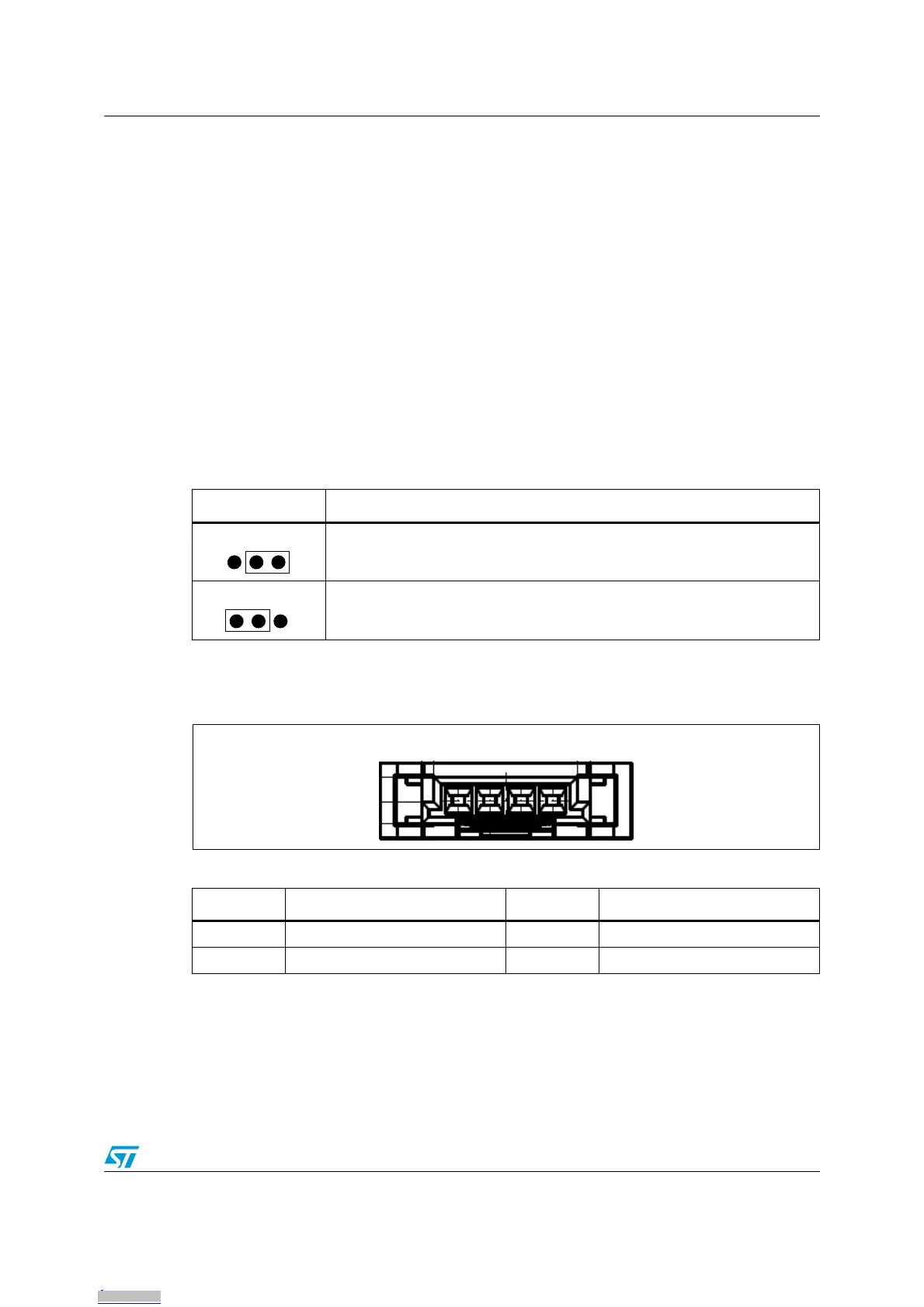
Jumper W1 is used to configure SWIM settings as described in Table 3.
For more information, please refer to user manual UM0470: STM8 SWIM communication
protocol and debug module.
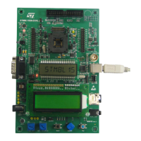
Figure 6. SWIM connector (top view)
Note: The SWIM connector of the STM8/128-EVAL board cannot be used.
Table 3. W1 jumper description
Configuration Description
Uses STM8S TS daughterboard SWIM connector (default setting)
Connect PD1of STM8S TS daughterboard device to resource of STM8S/128-
EVAL board.
Table 4. SWIM connector pin description
Pin number Description Pin number Description
1VDD 2PD1
3 GND 4 PA0 (RESET)
123
123
1 2 3 4
Downloaded from Arrow.com.Downloaded from Arrow.com.Downloaded from Arrow.com.Downloaded from Arrow.com.Downloaded from Arrow.com.Downloaded from Arrow.com.Downloaded from Arrow.com.Downloaded from Arrow.com.Downloaded from Arrow.com.Downloaded from Arrow.com.Downloaded from Arrow.com.