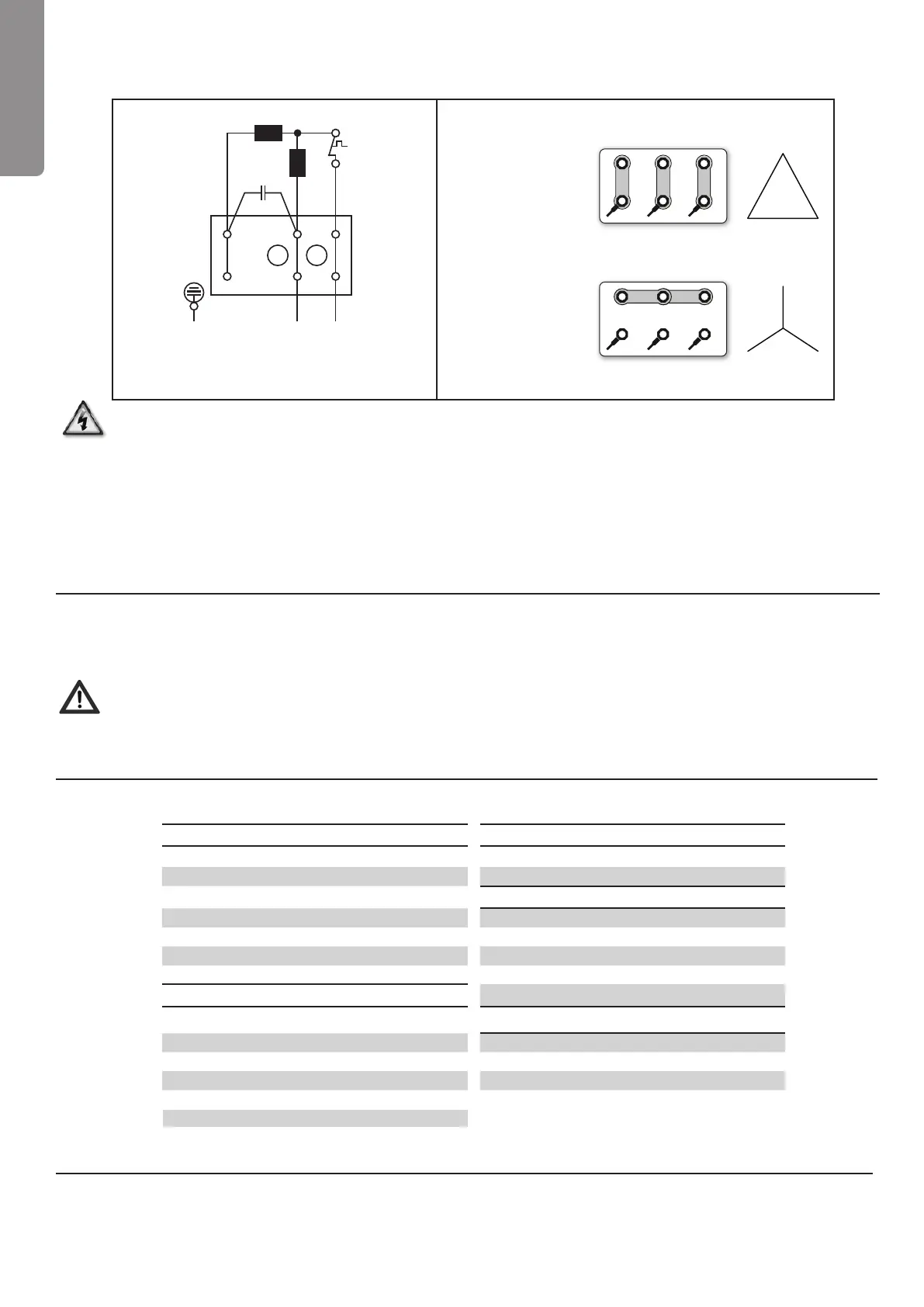
Single phase - Wiring diagram
220-240V/50Hz
Three phase - Wiring diagram
380-420V/50Hz
Three phase motors
wired to main voltage
of 3x230 Volt require
a DELTA connection
Three phase motors
wired to main voltage
of 3x400 Volt require
a STAR connection
Ha Main phase
Hi Auxiliary phase
TW Thermostatic protection switch
C Condenser
Make sure that you turn off the power supply when connecting the cables of the pump
Please check the turning direction of three-phase motors following each connection. If this does
not correspond to the arrow on the motor two connections in the junction must be reversed.
Every motor must be permanently grounded.
Connections which do not conform to the above mentioned safety instruction are not
covered by the warranty.
Section 6
Servicing
The pumps are designed to operate for many years without servicing. If a failure does occur, it
most likely will be a moving part of the pump.
Always disconnect the power supply to the pump before servicing.
The replacement of the electrical motor must be done by a professional.
Section 7
Troubleshooting
English
N LI
TW
Hi
Ha
C
PE
Pump will not prime Low ow / high lter pressure
No water in strainer pot Filter is dirty
Strainer pot lid is not tight Restriction in return line
Damaged lid O-ring
Low ow / low lter pressure
Water level is below skimmer Strainer basket or skimmer basket is clogged
Strainer basket or skimmer basket is clogged Clogged impeller
Closed valve in piping system Air leak in suction line
Air leak in suction line Restriction in suction line
Motor does not turn
Reverse rotation of motor (three phase only)
Power switch is off
Noisy pump
Circuit breaker has tripped Air leak in suction
Pump is off-mode of a timer controlled circuit Foreign matter in pump housing
Motor terminal connections are incorrect Cavitation
Motor shaft is locked by bad bearing
Impeller is locked by debris
Section 8
Technical data
Technical data as well as illustrated parts list can be found at the end of this manual.
W2
U2
U2
V1
V2
W1
W2 U2 V2
U2 V1 W1
4