SECTION TWO – Heater Installation
VV
VV
ee
ee
nn
nn
tt
tt
ii
ii
nn
nn
gg
gg
II
II
nn
nn
dd
dd
oo
oo
oo
oo
rr
rr
aa
aa
nn
nn
dd
dd
OO
OO
uu
uu
tt
tt
dd
dd
oo
oo
oo
oo
rr
r
r
SS
SS
hh
hh
ee
ee
ll
ll
tt
tt
ee
ee
rr
rr
II
II
nn
nn
ss
ss
tt
tt
aa
aa
ll
ll
ll
ll
aa
aa
tt
tt
ii
ii
oo
oo
nn
nn
ss
ss
––
––
CC
CC
oo
o
o
nn
nn
tt
tt
ii
ii
nn
nn
uu
uu
ee
ee
dd
dd
The heater require s suf ficient air for combustion and
ventilation. Choose a location that will avoid contami-
nation by chemical fumes.
NN
NN
OO
OO
TT
TT
EE
EE
::
::
Combustion air contaminated by corrosive
chemical fumes can damage the heater and will void
the warranty.
Combustion and Ventilation
Air Supply
For indoor installation, the heater requires air supply
openings for ventilation and combustion. The mini-
mum requirements are for two (2) openings: one 12
inches from the ceiling for ventilation air and one 12
inches from the floor for combustion air, in accordance
with the latest edition of the National Fuel Gas Code,
ANSI Z223.1., and any local codes that may apply.
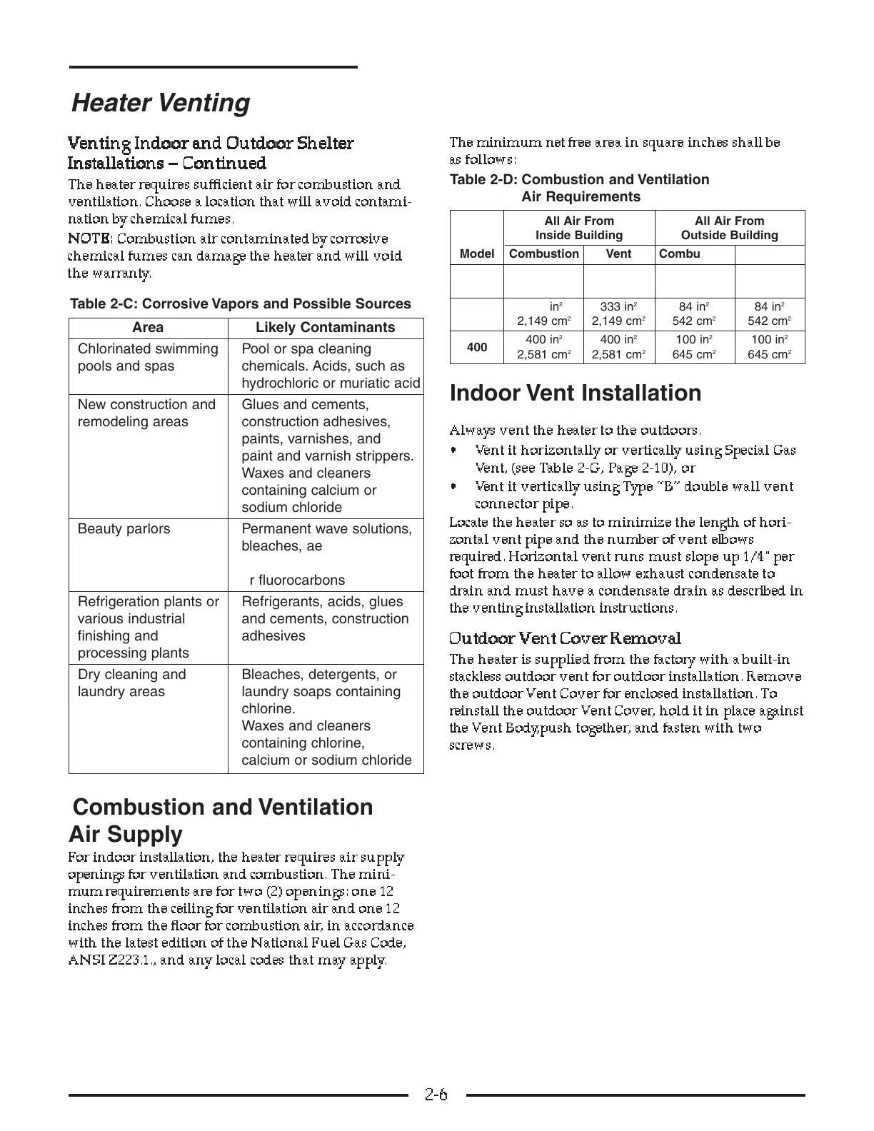
The minimum net free area in square inches shall be
as follows:
Table 2-D: Combustion and Ventilation
Air Requirements
Indoor Vent Installation
Always vent the heater to the outdoors.
• Vent it horizontally or vertically using Special Gas
Vent, (see Table 2-G, Page 2-10), or
• Vent it vertically using Type “B” double wall vent
connector pipe.
Locate the heater so as to minimize the length of hori-
zontal vent pipe and the number of vent elbows
required. Horizontal vent runs must slope up 1/4"per
foot from the heater to allow exhaust condensate to
drain and must have a condensate drain as described in
the venting installation instructions.
OO
OO
uu
uu
tt
tt
dd
dd
oo
oo
oo
oo
rr
rr
VV
VV
ee
ee
nn
nn
tt
tt
CC
CC
oo
oo
vv
vv
ee
ee
rr
rr
RR
RR
ee
ee
mm
mm
oo
oo
vv
vv
aa
aa
ll
ll
The heater is supplied from the factory with a built-in
stackless outdoor vent for outdoor installation. Remove
the outdoor Vent Cover for enclosed installation. To
reinstall the outdoor Vent Cover , hold it in place against
the V ent Body,push together, and fasten with two
screws.
2-6
Heater Venting
Area Likely Contaminants
Chlorinated swimming Pool or spa cleaning
pools and spas chemicals. Acids, such as
hydrochloric or muriatic acid
New construction and Glues and cements,
remodeling areas construction adhesives,
paints, varnishes, and
paint and varnish strippers.
Waxes and cleaners
containing calcium or
sodium chloride
Beauty parlors Permanent wave solutions,
bleaches, aerosol cans
containing chlorocarbons
or fluorocarbons
Refrigeration plants or Refrigerants, acids, glues
various industrial and cements, construction
finishing and adhesives
processing plants
Dry cleaning and Bleaches, detergents, or
laundry areas laundry soaps containing
chlorine.
Waxes and cleaners
containing chlorine,
calcium or sodium chloride
Table 2-C: Corrosive Vapors and Possible Sources
All Air From All Air From
Inside Building Outside Building
Model Combustion Vent Combustion Vent
200
200 in
2
200 in
2
50 in
2
50 in
2
1,291 cm
2
1,291 cm
2
323 cm
2
323 cm
2
333
333 in
2
333 in
2
84 in
2
84 in
2
2,149 cm
2
2,149 cm
2
542 cm
2
542 cm
2
400
400 in
2
400 in
2
100 in
2
100 in
2
2,581 cm
2
2,581 cm
2
645 cm
2
645 cm
2