SECTION TWO – Heater Installation
Power Supply Requirements
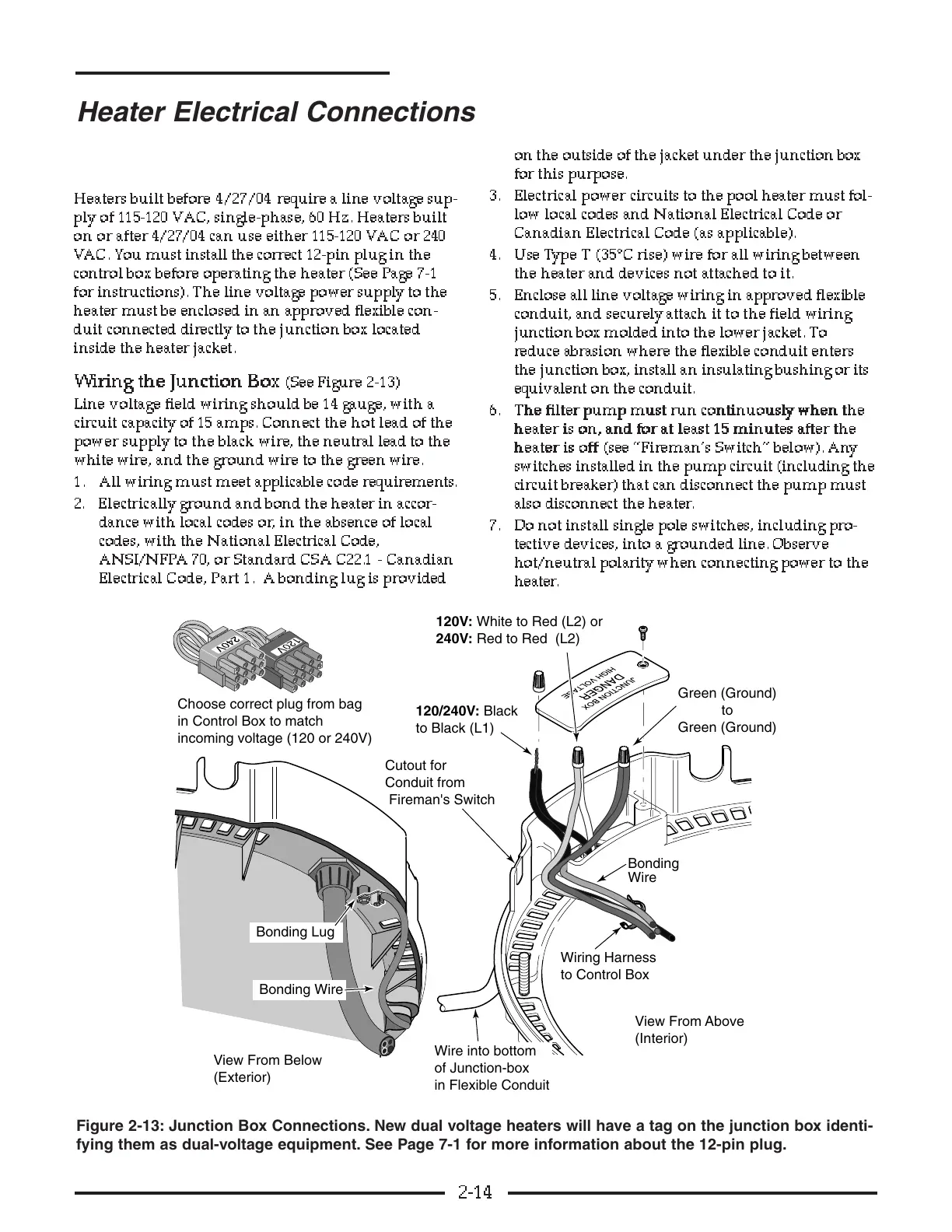
Heaters built before 4/27/04 require a line voltage sup-
ply of 115-120 VAC, single-phase, 60 Hz. Heaters built
on or after 4/27/04 can use either 115-120 VAC or 240
VAC. You must install the correct 12-pin plug in the
control box before operating the heater (See Page 7-1
for instructions). The line voltage power supply to the
heater must be enclosed in an approved flexible con-
duit connected directly to the junction box located
inside the heater jacket.
WW
WW
ii
ii
rr
rr
ii
ii
nn
nn
gg
gg
tt
tt
hh
hh
ee
ee
JJ
JJ
uu
uu
nn
nn
cc
cc
tt
tt
ii
ii
oo
oo
nn
nn
BB
BB
oo
oo
xx
xx
(See Figure 2-13)
Line voltage field wiring should be 14 gauge, with a
circuit capacity of 15 amps. Connect the hot lead of the
power supply to the black wire, the neutral lead to the
white wire, and the ground wire to the green wire.
1. All wiring must meet applicable code requirements.
2. Electrically ground and bond the heater in accor-
dance with local codes or, in the absence of local
codes, with the National Electrical Code,
ANSI/NFPA 70, or Standard CSA C22.1 - Canadian
Electrical Code, Part 1. A bonding lug is provided
on the outside of the jacket under the junction box
for this purpose.
3. Electrical power circuits to the pool heater must fol-
low local codes and National Electrical Code or
Canadian Electrical Code (as applicable).
4. Use Type T (35°C rise) wire for all wiring between
the heater and devices not attached to it.
5. Enclose all line voltage wiring in approved flexible
conduit, and securely attach it to the field wiring
junction box molded into the lower jacket. To
reduce abrasion where the flexible conduit enters
the junction box, install an insulating bushing or its
equivalent on the conduit.
6. TT
TT
hh
hh
ee
ee
ff
ff
ii
ii
ll
ll
tt
tt
ee
ee
rr
rr
pp
pp
uu
uu
mm
mm
pp
pp
mm
mm
uu
uu
ss
ss
tt
tt
rr
rr
uu
uu
nn
nn
cc
cc
oo
oo
nn
nn
tt
tt
ii
ii
nn
nn
uu
uu
oo
oo
uu
uu
ss
ss
ll
ll
yy
yy
ww
ww
hh
hh
ee
ee
nn
nn
tt
tt
hh
hh
ee
ee
hh
hh
ee
ee
aa
aa
tt
tt
ee
ee
rr
rr
ii
ii
ss
ss
oo
oo
nn
nn
,,
,,
aa
aa
nn
nn
dd
dd
ff
ff
oo
oo
rr
rr
aa
aa
tt
tt
ll
ll
ee
ee
aa
aa
ss
ss
tt
tt
11
11
55
55
mm
mm
ii
ii
nn
nn
uu
uu
tt
tt
ee
ee
ss
ss
aa
aa
ff
ff
tt
tt
ee
ee
rr
rr
tt
tt
hh
hh
ee
ee
hh
hh
ee
ee
aa
aa
tt
tt
ee
ee
rr
rr
ii
ii
ss
ss
oo
oo
ff
ff
ff
ff
(see “Fireman’s Switch” below). Any
switches installed in the pump circuit (including the
circuit breaker) that can disconnect the pump must
also disconnect the heater.
7. Do not install single pole switches, including pro-
tective devices, into a grounded line. Observe
hot/neutral polarity when connecting power to the
heater .
2-14
Heater Electrical Connections