SECTION TWO – Heater Installation
FF
FF
ii
ii
rr
rr
ee
ee
mm
mm
aa
aa
nn
nn
’’
’’
ss
ss
SS
SS
ww
ww
ii
ii
tt
tt
cc
cc
hh
hh
//
//
RR
RR
ee
ee
mm
mm
oo
oo
tt
tt
ee
ee
(See Figure 2-14)
NN
NN
OO
OO
TT
TT
EE
EE
::
::
If, while there is line voltage connected to the
heater, you touch either line voltage terminal with any
24VAC wire that is connected to the control board
(including the Fireman’s Switch jumper), you will imme-
diately destroy the control board and void the warranty.
If the filter pump is controlled by a time clock, a low-
voltage Fireman’s Switch that switches off the heater
at least 15 minutes before shutting off the pump should
be installed. The Fireman’s Switch completes the circuit
for the low voltage safety switches; it DOES NOT get
any power from the 1 15 volt power supply.
NN
NN
OO
OO
TT
TT
EE
EE
::
::
When using a timer and Fireman’s Switch, the
heater’s power supply should come from the load side
of the timer.
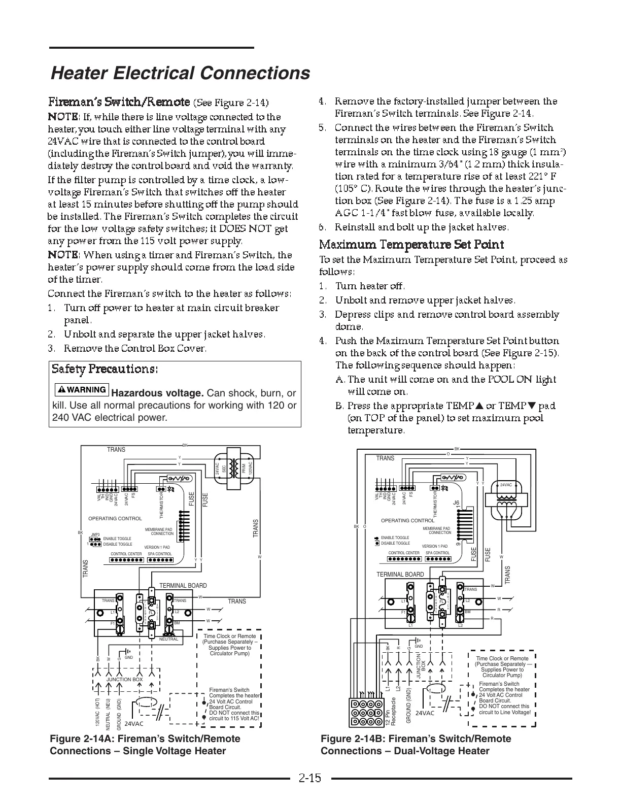
Connect the Fireman’s switch to the heater as follows:
1. Turn off power to heater at main circuit breaker
panel.
2. Unbolt and separate the upper jacket halves.
3. Remove the Control Box Cover.
4. Remove the factory-installed jumper between the
Fireman’s Switch terminals. See Figure 2-14.
5. Connect the wires between the Fireman’s Switch
terminals on the heater and the Fireman’s Switch
terminals on the time clock using 18 gauge (1 mm
2
)
wire with a minimum 3/64" (1.2 mm) thick insula-
tion rated for a temperature rise of at least 221° F
(105° C). Route the wires through the heater’s junc-
tion box (See Figure 2-14). The fuse is a 1.25 amp
AGC 1-1/4"fast blow fuse, available locally.
6. Reinstall and bolt up the jacket halves.
MM
MM
aa
aa
xx
xx
ii
ii
mm
mm
uu
uu
mm
mm
TT
TT
ee
ee
mm
mm
pp
pp
ee
ee
rr
rr
aa
aa
tt
tt
uu
uu
rr
rr
ee
ee
SS
SS
ee
ee
tt
tt
PP
PP
oo
oo
ii
ii
nn
nn
tt
tt
To set the Maximum Temperature Set Point, proceed as
follows:
1. Turn heater off.
2. Unbolt and remove upper jacket halves.
3. Depress clips and remove control board assembly
dome.
4. Push the Maximum Temperature Set Point button
on the back of the control board (See Figure 2-15).
The following sequence should happen:
A. The unit will come on and the POOL ON light
will come on.
B. Press the appropriate TEMP
▲
or TEMP
▼
pad
(on TOP of the panel) to set maximum pool
temperature.
2-15
Heater Electrical Connections
Board Circuit.
Board Circuit.