SECTION FOUR – Routine Maintenance and Professional Servicing
LL
LL
oo
oo
cc
cc
aa
aa
tt
tt
ii
ii
oo
oo
nn
nn
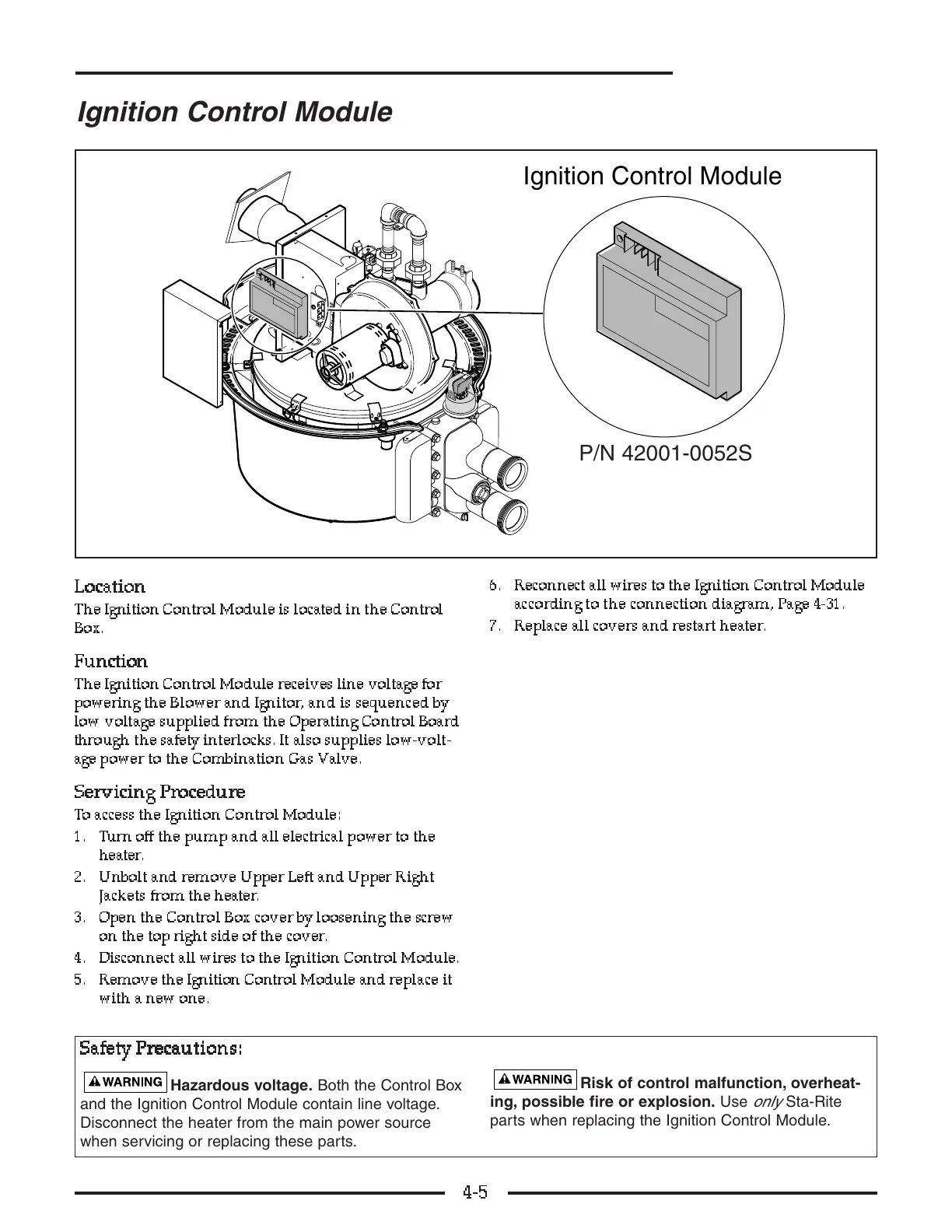
The Ignition Control Module is located in the Control
Box.
FF
FF
uu
uu
nn
nn
cc
cc
tt
tt
ii
ii
oo
oo
nn
nn
The Ignition Control Module receives line voltage for
powering the Blower and Ignitor, and is sequenced by
low voltage supplied from the Operating Control Board
through the safety interlocks. It also supplies low-volt-
age power to the Combination Gas Valve.
SS
SS
ee
ee
rr
rr
vv
vv
ii
ii
cc
cc
ii
ii
nn
nn
gg
gg
PP
PP
rr
rr
oo
oo
cc
cc
ee
ee
dd
dd
uu
uu
rr
rr
ee
ee
To access the Ignition Control Module:
1. Turn off the pump and all electrical power to the
heater .
2. Unbolt and remove Upper Left and Upper Right
Jackets from the heater.
3. Open the Control Box cover by loosening the screw
on the top right side of the cover.
4. Disconnect all wires to the Ignition Control Module.
5. Remove the Ignition Control Module and replace it
with a new one.
6. Reconnect all wires to the Ignition Control Module
according to the connection diagram, Page 4-31.
7. Replace all covers and restart heater.
4-5
Ignition Control Module
SS
SS
aa
aa
ff
ff
ee
ee
tt
tt
yy
yy
PP
PP
rr
rr
ee
ee
cc
cc
aa
aa
uu
uu
tt
tt
ii
ii
oo
oo
nn
nn
ss
ss
::
::
Hazardous voltage. Both the Control Box
and the Ignition Control Module contain line voltage.
Disconnect the heater from the main power source
when servicing or replacing these parts.
Risk of control malfunction, overheat-
ing, possible fire or explosion. Use
only
Sta-Rite
parts when replacing the Ignition Control Module.
P/N 42001-0052S