SECTION TWO – Heater Installation
HH
HH
oo
oo
rr
rr
ii
ii
zz
zz
oo
oo
nn
nn
tt
tt
aa
aa
ll
ll
oo
oo
rr
rr
VV
VV
ee
ee
rr
rr
tt
tt
ii
ii
cc
cc
aa
aa
ll
ll
VV
VV
ee
ee
nn
nn
tt
tt
ii
ii
nn
nn
gg
gg
--
--
PP
PP
oo
oo
ss
ss
ii
ii
tt
tt
ii
ii
vv
vv
ee
ee
PP
PP
rr
rr
ee
ee
ss
ss
ss
ss
uu
uu
rr
rr
ee
ee
(See Figures 2-9, 2-10 and 2-11)
Vent the heater either horizontally or vertically using
one of the 4-inch Special Gas Vent Pipes listed on Page
2-10 (Table 2-G). Install the vent pipe in accordance
with local c odes and the provisions of the National Fuel
Gas Code, ANSI Z223.1 (U.S.) or Standard CSA-B149.1
(Canada), and the vent manufacturer’s instructions.
DD
DD
oo
oo
nn
nn
oo
oo
tt
tt
use a draft hood with this heater. Use one of the
special gas vents specified in Table 2-G (Page 2-11) for
positive-pressure venting of this heater – do not use
any other vent with it. Install the vent according to the
vent manufacturer’s detailed instr uctions.
Maintain clearance between the vent pipe and com-
bustible surfaces according to the vent manufacture r’s
instructions and code requirements. Do not place any
insulating materials around the vent or inside the
required clear air space surrounding the vent. See Table
2-H (Page 2-12) for maximum permissable vent lengths.
See Table 2-J (Page 2-12) for vent thimbles and termi -
nals listed in U.S.
CC
CC
oo
oo
nn
nn
nn
nn
ee
ee
cc
cc
tt
tt
ii
ii
nn
nn
gg
gg
SS
SS
pp
pp
ee
ee
cc
cc
ii
ii
aa
aa
ll
ll
GG
GG
aa
aa
ss
ss
VV
VV
ee
ee
nn
nn
tt
tt
tt
tt
oo
oo
tt
tt
hh
hh
ee
ee
HH
HH
ee
ee
aa
aa
tt
tt
ee
ee
rr
rr
MM
MM
ee
ee
tt
tt
aa
aa
ll
ll
ll
ll
ii
ii
cc
cc
::
::
1. O rder an Appliance Adapter Kit:
Sta-Rite Part No. 77707-0086 for Saf-T Vent
®
or
Saf-T Ve nt
®
CI.
Sta-Rite Part No. 77707-0087 for Z-Vent.
2. Remove the outside Vent Cover.
SS
SS
uu
uu
rr
rr
ff
ff
aa
aa
cc
cc
ee
ee
PP
PP
rr
rr
ee
ee
pp
pp
aa
aa
rr
rr
aa
aa
tt
tt
ii
ii
oo
oo
nn
nn
::
::
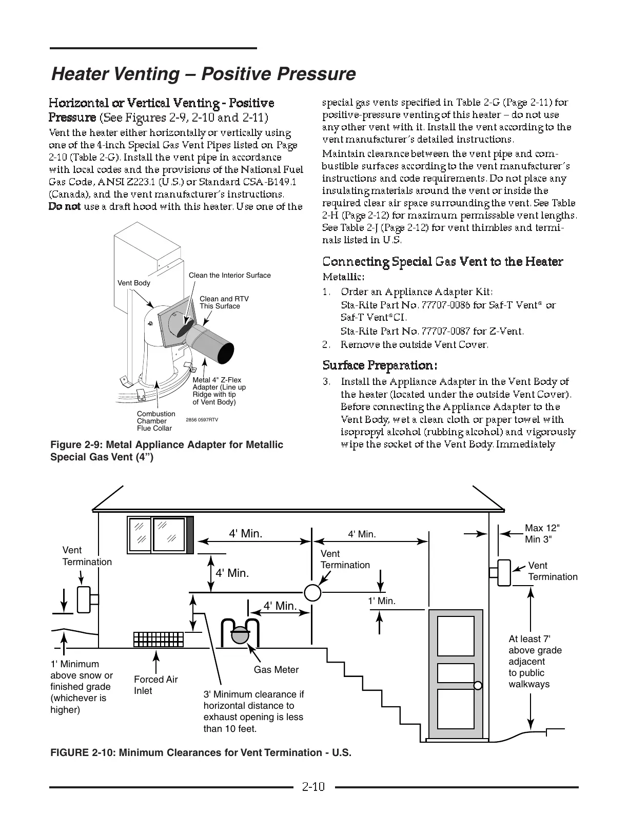
3 . Install the Appliance Adapter in the Vent Body of
the heater (located under the outside Vent Cover).
Before connecting the Appliance Adapter to the
Vent Body, wet a clean cloth or paper towel with
isopropyl alcohol (rubbing alcohol) and vigorously
wipe the socket of the Vent Body. Immediately
2-10
Heater Venting – Positive Pressure
1' Min.
4' Min.
4' Min.
4' Min.
4' Min.
than 10 feet.