SECTION TWO – Heater Installation
• at least 4 feet below or horizontally from, or 1 foot
above, any doors or windows or gravity air inlet to
a building.
• At least 3 feet above any forced air inlet located
within 10 feet.
• At least 4 feet horizontally from electric meters,
gas meters, regulators and relief equipment.
• At least 7 feet above grade adjacent to walkways
or similar traffic areas.
Allow at least 3 feet vertical clearance over vent termi-
nation when terminating under an overhang or deck.
Avoid corners or alcoves where snow or wind could
have an effect. Exhaust may affect shrubbery and some
building materials. Keep shrubbery away from termina-
tion. To prevent staining or deterioration, sealing or
shielding exposed surfaces may be required.
CC
CC
aa
aa
nn
nn
aa
aa
dd
dd
aa
aa
::
::
Vent Termination – Horizontal (See Table 2-J).
Use a listed wall thimble and vent terminal from
Table 2-J.
The terminal must be located
• at least 10 feet (3.3 M) from any opening into a
building.
• at least 12"(.3 M) above finished grade or the nor -
mally expected snow accumulation level, whichev -
er is higher
• At least 4 feet (1.2 M) horizontally from electric
meters, gas meters, regulators and relief equipment
• At least 7 feet (2.1 M) above grade adjacent to
walkways or similar traffic areas.
Allow at least 4 feet (1.2 M) vertical clearance over vent
termination when terminating under an overhang or
deck.
Avoid corners or alcoves where snow or wind could
have an effect. Exhaust may affect shrubbery and some
building materials. Keep shrubbery away from termina-
tion. To prevent staining or deterioration, sealing or
shielding exposed surfaces may be required.
Fire Hazard. Do not run the heater vent
into a common vent with any other appliance. Do
not run the Special Gas Vent into, through, or within
any active vent such as a factory built or masonry
chimney.
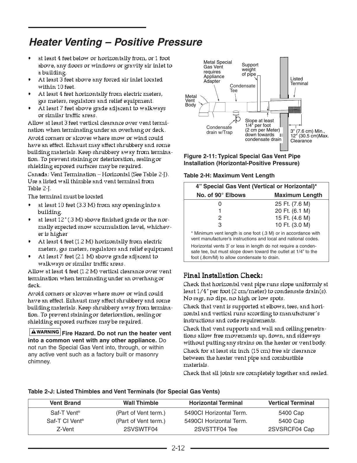
Figure 2-11: Typical Special Gas Vent Pipe
Installation (Horizontal-Positive Pressure)
Table 2-H: Maximum Vent Length
FF
FF
ii
ii
nn
nn
aa
aa
ll
ll
II
II
nn
nn
ss
ss
tt
tt
aa
aa
ll
ll
ll
ll
aa
aa
tt
tt
ii
ii
oo
oo
nn
nn
CC
CC
hh
hh
ee
ee
cc
cc
kk
kk
::
::
Check that horizontal vent pipe runs slope uniformly at
least 1/4"per foot (2 cm/meter) to condensate drain(s).
No sags, no dips, no high or low spots.
Check that vent is supported at elbows, tees, and hori-
zontal and vertical runs according to manufacturer’s
instructions and code requirements.
Check that vent supports and wall and ceiling penetra-
tions allow free movements up, down, and sideways
without putting any strains on the heater or vent body.
Check for at least six inch (15 cm) free air clearance
between the heater vent pipe and combustible
materials.
Check that all joints are completely together and sealed.
2-12
Heater Venting – Positive Pressure
12" (30.5 cm)Max.
4” Special Gas Vent (Vertical or Horizontal)*
No. of 90° Elbows Maximum Length
0 25 Ft. (7.6 M)
1 20 Ft. (6.1 M)
2 15 Ft. (4.6 M)
3 10 Ft. (3.0 M)
* Minimum vent length is one foot (.3 M) or in accordance with
vent manufacturer’s instructions and local and national codes.
Horizontal vents 3’ or less in length do not require a conden-
sate tee, but must slope down toward the outlet at 1/4” to the
foot (.8cm/M) to allow condensate to drain.
Vent Brand Wall Thimble Horizontal Terminal Vertical Terminal
Saf-T Vent
®
(Part of Vent term.) 5490CI Horizontal Term. 5400 Cap
Saf-T CI Vent
®
(Part of Vent term.) 5490CI Horizontal Term. 5400 Cap
Z-Vent 2SVSWTF04 2SVSTTF04 Tee 2SVSRCF04 Cap
Table 2-J: Listed Thimbles and Vent Terminals (for Special Gas Vents)