SECTION FOUR – Routine Maintenance and Professional Servicing
LL
LL
oo
oo
cc
cc
aa
aa
tt
tt
ii
ii
oo
oo
nn
nn
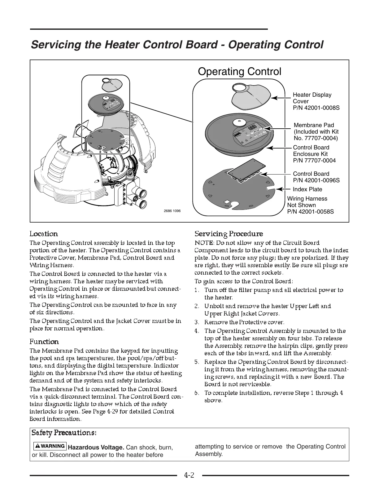
The Operating Control assembly is located in the top
portion of the heater. The Operating Control contains a
Protective Cover, Membrane Pad, Control Board a nd
Wiring Harness.
The Control Board is connected to the heater via a
wiring harness. The heater may be serviced with
Operating Control in place or dismounted but connect-
ed via its wiring harness.
The Operating Control can be mounted to face in any
of six directions.
The Operating Control and the Jacket Cover must be in
place for normal operation.
FF
FF
uu
uu
nn
nn
cc
cc
tt
tt
ii
ii
oo
oo
nn
nn
The Membrane Pad contains the keypad for inputting
the pool and spa temperatures, the pool/spa/off but-
tons, and displaying the digital temperature. Indicator
lights on the Membrane Pad show the status of heating
demand and of the system and safety interlocks.
The Membrane Pad is connected to the Control Board
via a quick-disconnect terminal. The Control Board con-
tains diagnostic lights to show which of the safety
interlocks is open. See Page 4-29 for detailed Control
Board information.
SS
SS
ee
ee
rr
rr
vv
vv
ii
ii
cc
cc
ii
ii
nn
nn
gg
gg
PP
PP
rr
rr
oo
oo
cc
cc
ee
ee
dd
dd
uu
uu
rr
rr
ee
ee
NN
NN
OO
OO
TT
TT
EE
EE
::
::
Do not allow any of the Circuit Board
Component leads to the circuit board to touch the index
plate. Do not force any plugs; they are polarized. If they
are right, they will assemble easily. Be sure all plugs are
connected to the correct sockets.
To gain access to the Control Board:
1. Turn off the filter pump and all electrical power to
the heater.
2. Unbolt and remove the heater Upper Left and
Upper Right Jacket Covers.
3. Remove the Protective cover.
4. The Operating Control Assembly is mounted to the
top of the heater assembly on four tabs. To release
the Assembly, remove the hairpin clips, gently press
each of the tabs inward, and lift the Assembly.
5. Replace the Operating Control Board by disconnect-
ing it from the wiring harness, removing the mount-
ing screws, and replacing it with a new Board. The
Board i s not serviceable.
6. To complete installation, reverse Steps 1 through 4
above.
4-2
No. 77707-0004)