SECTION FOUR – Routine Maintenance and Professional Servicing
II
II
nn
nn
ss
ss
tt
tt
rr
rr
uu
uu
cc
cc
tt
tt
ii
ii
oo
oo
nn
nn
ss
ss
FF
FF
oo
oo
rr
rr
CC
CC
hh
hh
ee
ee
cc
cc
kk
kk
ii
ii
nn
nn
gg
gg
tt
tt
hh
hh
ee
ee
GG
GG
aa
aa
ss
ss
PP
PP
rr
rr
ee
ee
ss
ss
ss
ss
uu
uu
rr
rr
ee
ee
TT
TT
hh
hh
rr
rr
oo
oo
uu
uu
gg
gg
hh
hh
tt
tt
hh
hh
ee
ee
CC
CC
oo
oo
mm
mm
bb
bb
ii
ii
nn
nn
aa
aa
tt
tt
ii
ii
oo
oo
nn
nn
GG
GG
aa
aa
ss
ss
CC
CC
oo
oo
nn
nn
tt
tt
rr
rr
oo
oo
ll
ll
VV
VV
aa
aa
ll
ll
vv
vv
ee
ee
TT
TT
hh
hh
ee
ee
ss
ss
ee
ee
ii
ii
nn
nn
ss
ss
tt
tt
rr
rr
uu
uu
cc
cc
tt
tt
ii
ii
oo
oo
nn
nn
ss
ss
aa
aa
rr
rr
ee
ee
ff
ff
oo
oo
rr
rr
tt
tt
hh
hh
ee
ee
uu
uu
ss
ss
ee
ee
oo
oo
ff
ff
qq
qq
uu
uu
aa
aa
ll
ll
ii
ii
ff
ff
ii
ii
ee
ee
dd
dd
ss
ss
ee
ee
rr
rr
vv
vv
ii
ii
cc
cc
ee
ee
tt
tt
ee
ee
cc
cc
hh
hh
nn
nn
ii
ii
cc
cc
ii
ii
aa
aa
nn
nn
ss
ss
oo
oo
nn
nn
ll
ll
yy
yy
!!
!!
DD
DD
oo
oo
nn
nn
oo
oo
tt
tt
aa
aa
tt
tt
tt
tt
ee
ee
mm
mm
pp
pp
tt
tt
tt
tt
hh
hh
ii
ii
ss
ss
pp
pp
rr
rr
oo
oo
cc
cc
ee
ee
dd
dd
uu
uu
rr
rr
ee
ee
uu
uu
nn
nn
ll
ll
ee
ee
ss
ss
ss
ss
yy
yy
oo
oo
uu
uu
hh
hh
aa
aa
vv
vv
ee
ee
bb
bb
ee
ee
ee
ee
nn
nn
tt
tt
rr
rr
aa
aa
ii
ii
nn
nn
ee
ee
dd
dd
aa
aa
nn
nn
dd
dd
cc
cc
ee
ee
rr
rr
tt
tt
ii
ii
ff
ff
ii
ii
ee
ee
dd
dd
ii
ii
nn
nn
tt
tt
hh
hh
ee
ee
cc
cc
aa
aa
rr
rr
ee
ee
aa
aa
nn
nn
dd
dd
rr
rr
ee
ee
pp
pp
aa
aa
ii
ii
rr
rr
oo
oo
ff
ff
gg
gg
aa
aa
ss
ss
--
--
ff
ff
ii
ii
rr
rr
ee
ee
dd
dd
aa
aa
pp
pp
pp
pp
ll
ll
ii
ii
aa
aa
nn
nn
cc
cc
ee
ee
ss
ss
!!
!!
DD
DD
oo
oo
nn
nn
oo
oo
tt
tt
aa
aa
tt
tt
tt
tt
ee
ee
mm
mm
pp
pp
tt
tt
tt
tt
hh
hh
ii
ii
ss
ss
pp
pp
rr
rr
oo
oo
cc
cc
ee
ee
dd
dd
uu
uu
rr
rr
ee
ee
ii
ii
ff
ff
tt
tt
hh
hh
ee
ee
ff
ff
oo
oo
ll
ll
ll
ll
oo
oo
ww
ww
ii
ii
nn
nn
gg
gg
ii
ii
nn
nn
ss
ss
tt
tt
rr
rr
uu
uu
cc
cc
--
--
tt
tt
ii
ii
oo
oo
nn
nn
ss
ss
aa
aa
rr
rr
ee
ee
cc
cc
oo
oo
nn
nn
ff
ff
uu
uu
ss
ss
ii
ii
nn
nn
gg
gg
!!
!!
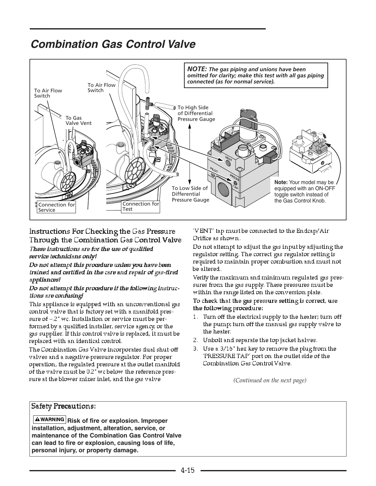
This appliance is equipped with an unconventional gas
control valve that is factory set with a manifold pres-
sure of –.2"wc. Installation or service must be per-
formed by a qualified installer, service agency, or the
gas supplier. If this control valve is replaced, it must be
replaced with an identical control.
The Combination Gas Valve incorporates dual shut-off
valves and a negative-pressure regulator. For proper
operation, the regulated pressure at the outlet manifold
of the valve must be 0.2" wc below the reference pres-
sure at the blower mixer inlet, and the gas valve
‘VENT’ tap must be connected to the Endcap/Air
Orifice as shown.
Do not attempt to adjust the gas input by adjusting the
regulator setting. The correct gas regulator setting is
required to maintain proper combustion and must not
be altered.
Verify the maximum and minimum regulated gas pres-
sures from the gas supply. These pressures must be
within the range listed on the conversion plate.
TT
TT
oo
oo
cc
cc
hh
hh
ee
ee
cc
cc
kk
kk
tt
tt
hh
hh
aa
aa
tt
tt
tt
tt
hh
hh
ee
ee
g
g
gg
aa
aa
ss
ss
pp
pp
rr
rr
ee
ee
ss
ss
ss
ss
uu
uu
rr
rr
ee
ee
ss
ss
ee
ee
tt
tt
tt
tt
ii
ii
nn
nn
gg
gg
ii
ii
ss
ss
cc
cc
oo
oo
rr
rr
rr
rr
ee
ee
cc
cc
tt
tt
,,
,,
uu
uu
ss
ss
ee
ee
tt
tt
hh
hh
ee
ee
ff
ff
oo
oo
ll
ll
ll
ll
oo
oo
ww
ww
ii
ii
nn
nn
gg
gg
pp
pp
rr
rr
oo
oo
cc
cc
ee
ee
dd
dd
uu
uu
rr
rr
ee
ee
::
::
1. Turn off the electrical supply to the heater; turn off
the pump; turn off the manual gas supply valve to
the heater.
2. Unbolt and separate the top jacket halves.
3. Use a 3/16"hex key to remove the plug from the
‘PRESSURE TAP’ port on the outlet side of the
Combination Gas Control Valve.
(Continued on the next page)
4-15
connected (as for normal service).
the Gas Control Knob.
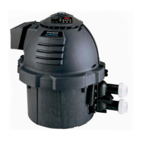
Combination Gas Control Valve
SS
SS
aa
aa
ff
ff
ee
ee
tt
tt
yy
yy
PP
PP
rr
rr
ee
ee
cc
cc
aa
aa
uu
uu
tt
tt
ii
ii
oo
oo
nn
nn
ss
ss
::
::
Risk of fire or explosion. Improper
installation, adjustment, alteration, service, or
maintenance of the Combination Gas Control Valve
can lead to fire or explosion, causing loss of life,
personal injury, or property damage.