SECTION FOUR – Routine Maintenance and Professional Servicing
22
22
..
..
MM
MM
aa
aa
ii
ii
nn
nn
BB
BB
uu
uu
nn
nn
dd
dd
ll
ll
ee
ee
::
::
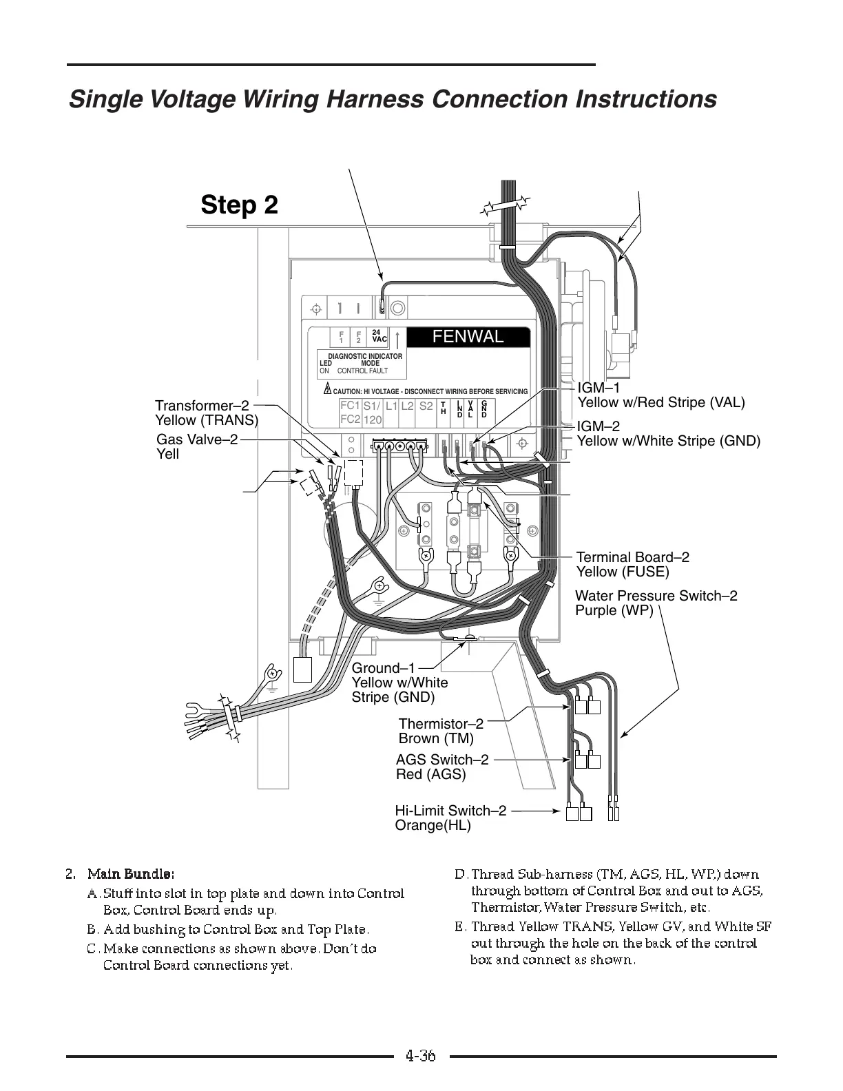
A. Stuff into slot in top plate and down into Control
Box, Control Board ends up.
B. Add bushing to Control Box and To p Plate.
C. Make connections as shown above. Don’t do
Control Board connections yet.
D. Thread Sub-harness (TM, AGS, HL, WP,) down
through bottom of Control Box and out to AGS,
Thermistor, W ater Pressure Switch, etc.
E . Thread Yellow TRANS, Yellow GV, and White SF
out through the hole on the back of the contr ol
box and connect as shown.
4-36
Single Voltage Wiring Harness Connection Instructions