AC S.A. All rights reserved. Any unauthorized copying, reproduction, publishing, dissemination, disclosing or other use of information presented herein, in whole or as part, particularly photographs,
drawings, trademarks, etc., may lead to prosecution or civil proceedings.
8
Engi
ne
manufac
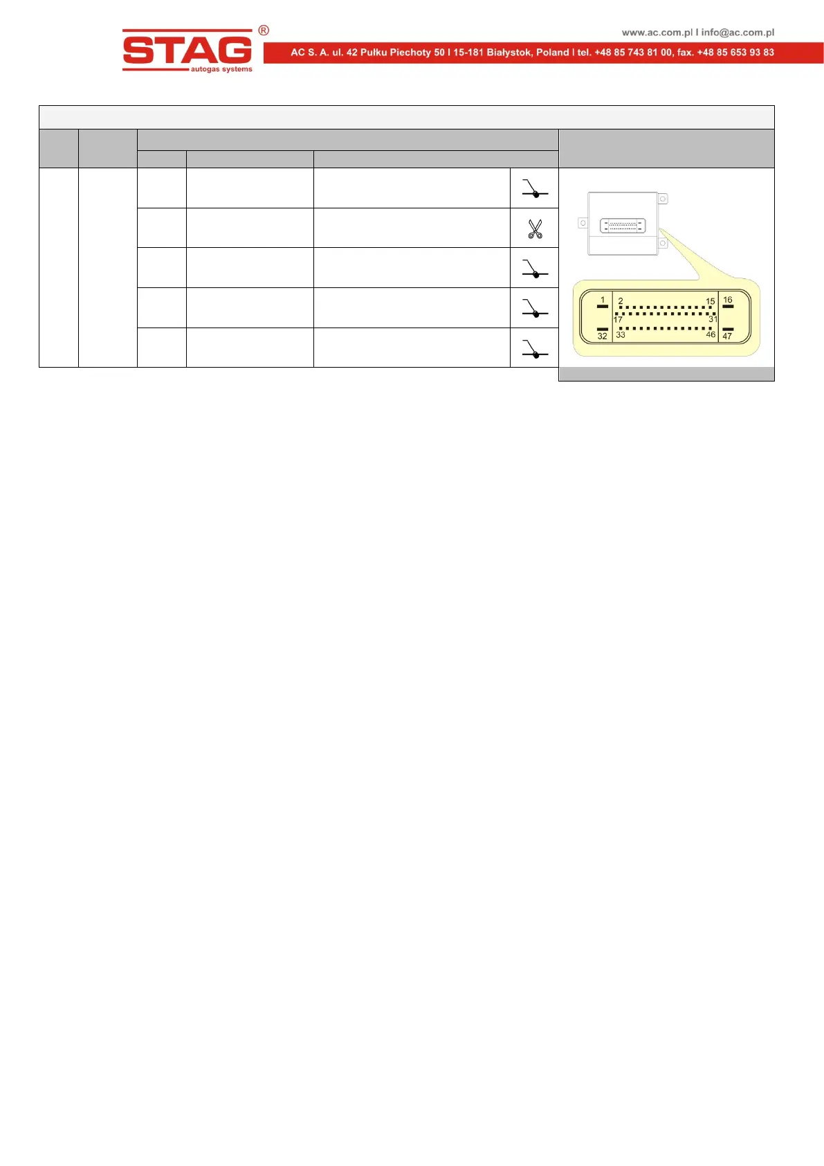
Fuel pump controller harness
Installation notes
Pin No. Wire colour Signal
2.4
2006
÷
2010
1 black GROUND
Connector of fuel pump controller
10 yellow Fuel pressure sensor signal
15 pink Ignition switch
32 red-white Battery +12V supply
47 grey Fuel pump control signal
5. Emulator start
Following the installation of FPE-A, adaptation must be performed.
1. Start the engine on petrol and keep it on idle until the rated operating temperature is
reached.
2. Make sure that the LPG/CNG change-over switch is set in the petrol fuel mode and stop
the engine.
3. Turn off the ignition switch.
4. Disconnect the FPE-A from the harness female connector, wait min. 5s and reconnect
the emulator. When the rubber cover on the connector is pulled off, an lit internal red LED
should be seen.
5. Turn on and turn off the ignition switch three times within 30s after emulator connection
to the harness socket. The internal red LED should start flashes slowly.
6. Start the engine. The internal red LED should start flashes fast.
7. Leave the car on idle for about 2 minutes until the internal red LED light stops flashing
and lights up permanently.
8. Switch car to gas and wait until the LED light will shut down. This means that the
adaptation process is completed.
When the adaptation is completed, the emulator is ready to work on LPG/CNG mode. If the
adaptation process is interrupted, the whole procedure must be restarted.
6. Notes
Correct operation of the emulator requires the following conditions to be met:
• The emulator should be connected in accordance with the wiring diagram and
recommendations of the table with unit versions.
• The emulator has been installed in the correct location (SCH1 for the ECM area and
SCH2 for the fuel pump controller area).
• The adaptation process has been completed successfully.