7
User’s manUal
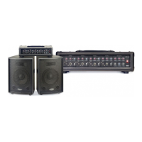
mPas 80/10 & mPas 80/12
How to operate the MPAS 80/10 or MPAS 80/12
Block Diagram
The block diagram is a visual representation of the internal links between the inputs and outputs, the
volume controls and the tone section as explained on page 5
Examples of Use
The diagrams on the next pages show how to connect the device in different situationsThe gures
mentionned on the diagrams are matching the gures written in the “block diagram” on page 6 (g. 2),
as well as those shown on the visual representation of the operating panel on page 4 (g.1).
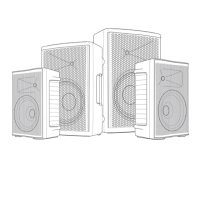
Modular PA extension
The PA system can be modulary extended by adding almost an innite number of active speaker sys-
tems, such as MPAS 80/1O, MPAS 80/12, or any MPAS 80/xx
N.B: In the diagrams, MPAS 80/10 and MPAS 80/12 are both symbolized by MPAS 80/xx
Whenever an optional extension is available, this is symbolized by the grey coloured MPAS 80/xx in the
example diagrams.
The PA system can be modulary extended by connecting any passive speaker enclosure with a mi-
nimum load impedance of 8 Ohms (MPS-10, MPS-12, or MPS xx, S 10, S 12, or S xx, or else)
to the «EXTSPK» output of this active speaker system
Following are examples of the most common situations where the MPAS 80/10 or MPAS 80/12 can be
used. The multiple mixing possibilities make our speaker usefull in many other situations.
Note:
Your dealer will assist you if you have any doubt about the technical specications or the use of this ne
product.