7
C
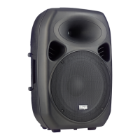
ontrols and Features
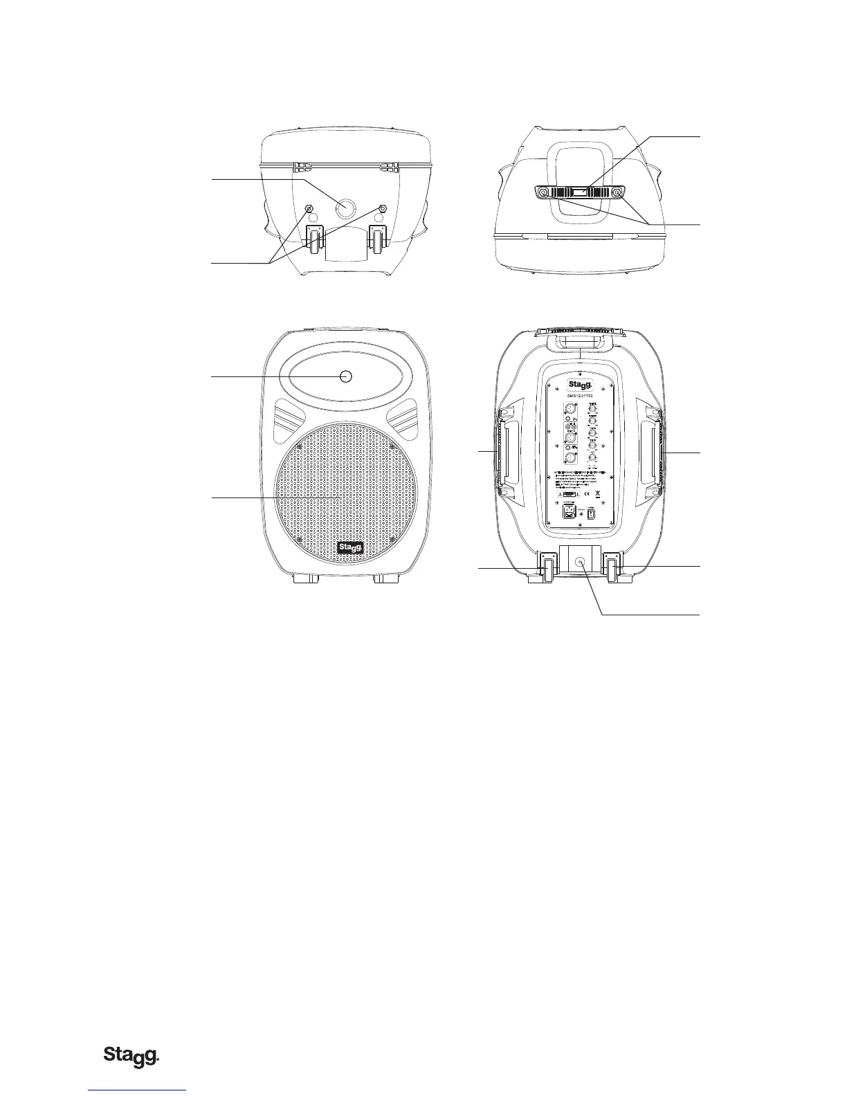
1.POLE MOUNT SOCKET-This socket is designed to fit a standard speaker
pole mount or tripod speaker stand.
2.RIGGING POINTS-This series speaker has rigging points . These points are
to be used to fly or suspend the speaker in the air by some means . Be sure
to follow the flying outlines.
3.HIGH FREQUENCY TRANSDUCER - This unit is used to reproduce the high
frequency response..
4.WOOFER-The high-powered woofer is used to reproduce the
midrange and low frequencies.
5.TRANSPORT HANDLE-This series speakers come with built-in
heavy-duty transportation handle . Use thi
s handle for secure
and easy transportation.
6.LUGGAGE-STYLE WHEELS-
.
allowing the unit to be easily
carried or pulled along on its luggage-style wheels
7.POLE MOUNT LOCKING BOLT- This pin is used to secure the
speaker in place when mounting the speaker in a pole mount
configuration . Always be sure to tighten down on the locking
bolt to prevent the speaker from shifting during use.
USB
MMC
SD
PLAY VOL + VOL- EQ SD POWE R
PAUSE N EXT P REV P RT USB STOP
AC 230V 50H z
POWER
GROUND
SMS15DP760LCD
HF:1.75 8 0W (4 4mm Ti d ome d riv e)
"
"
LF:15 300 W (75 mm vo ice c oil /60 oz magnet)
ACTIVE SO UND R EIN FOR CEM ENT SYS TEM
Interna l Swi tch M ode P owe r Sup ply(SMPS)
Revolut ion ary C las s-D Am pli fier Tech nol ogy
Nominal I mpe dan ce: 8 o hm
CLI P
MIC L EVEL
MIN MAX
LIN E LEVEL
MIN MAX
VOL UME
MIN MAX
-12
TRE BL E
+12
BAS S
-12
+12
POW ER
LIN E
OUT PUT
MIC
INP UT
R L
LIN E
INP UT
SMS15DP760LCD REAR PANEL DESCRIPTION
1
2
3
4
5
6
7
9
10
11
12
13
15
16
8
14
1. Mic XLR Input - Plug a mic directly into this port for public address
usage and let your voice be heard.
2. 1/4” MIC Input – Plug a mic directly into this port.
3. Balanced RCA Li ne Input – This connection is designed to accept
a balanced line input signal from a mixeror other line level device
with a balanced output jack. Use a balanced cable when the signal
cable length exceeds 15 feet, this will reduce excessive signal loss.
Be sure to connect only line level input devices such as mixers
and tape machines to this jack.
4. Balanced XLR Li ne Input – This connection is designed to
accept a balanced line input signal from a mixer or other line level
device with a balanced output jack. Use a balanced cable when
the signal cable length exceeds 15 feet, this will reduce excessive
signal loss.5.1/4” Line Output Jack – This jack is used to send
the incoming line level signal from either of the Line Level Inputs
Jacks to other powered speaker.
38
6. XLR LINE Output – Using a XLR cable, use this port to daisy chain from your this speaker to other powered
speaker.
7.Main Power Inlet – This connector is used to supply main power to the unit via the included detachable power
cord.
8.Fuse Holder – This housing stores the 3.15 amp GMA protective fuse. Always replace with the exact same type
fuse, unless otherwise instructed,
9. Microphone input Volume – This knob is used to increase or decrease the volume output on your speaker.
10. Line level input volume – This knob is used to regulate the output signal of theline level sou
rce connected to
the Line Level Inputs.
11. output volume – This knob is used to regulate the output signal being sent to other powered speaker.
12. Treble control – This knob is used to regulate the amount treble applied to the output signal. The maximum
amount of treble gain is +12dB and the maximum amount of treble decrease is -12dB. Turning the knob in a
counter-clockwise direction will decrease the amount of treble applied to a channel signal, turning the knob in a
clockwise direction will increase the amount of treble applied to a channel signal.
13. Bass Control – This kn
ob is used to regulate the amount bass applied to the
output signal. The maximum amount of bass gain is +12dB and the maximum amount of bass decrease is -12dB.
Turning the knob in a counter-clockwise direction will decrease the amount of bass applied to a channel signal,
turning the knob in a clockwise direction will increase the amount of bass applied to a channel signal.
14. Power indica tor led - LED lights up to indicate the speaker is on.
15. Clip Led - If this LED is lit it means your signal is clipping. To stop the signal from clipping lower the volume
to the point where the LED is blinking along with the bass beat.
16. AC VOLTOLTOLTAGEGE SELEELEELECTOTOR - This switch is used to change the operating voltage.
Operating voltage can be toggled between 115v or 230v/50~60Hz. Be sure the selector is set to the proper
voltage for your area before attempting to operate the unit. Always be sure main power is shut off before change
the position of the Voltage Selector Switch.
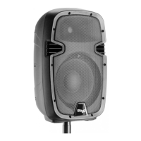
Controls and Features
1. POLE MOUNT SOCKET
This socket is designed to t a standard 35mm speaker pole mount or tripod speaker stand.
2. RIGGING POINTS
This series speaker has rigging points. These points are to be used to y or suspend the
speaker in the air by some means. Be sure to follow the ying outlines.
3. HIGH FREQUENCY TRANSDUCER
This unit is used to reproduce the high frequency response..
4. WOOFER
The high-powered woofer is used to reproduce the midrange and low frequencies.
5. TRANSPORT HANDLE
This series speakers come with built-in heavy-duty transportation handle .
Use this handle for secure and easy transportation.
6. LUGGAGE-STYLE WHEELS
allowing the unit to be easily carried or pulled along on its luggage-style wheels.
DO NOT USE ON STAIRS OR ROUGH SURFACE .
7. POLE MOUNT LOCKING BOLT
This pin is used to secure the speaker in place when mounting the speaker in a pole
mount con guration . Always be sure to tighten down on the locking
 Loading...